Kia Optima DL3: Timing System / Timing Chain
Components and components location
| Components |
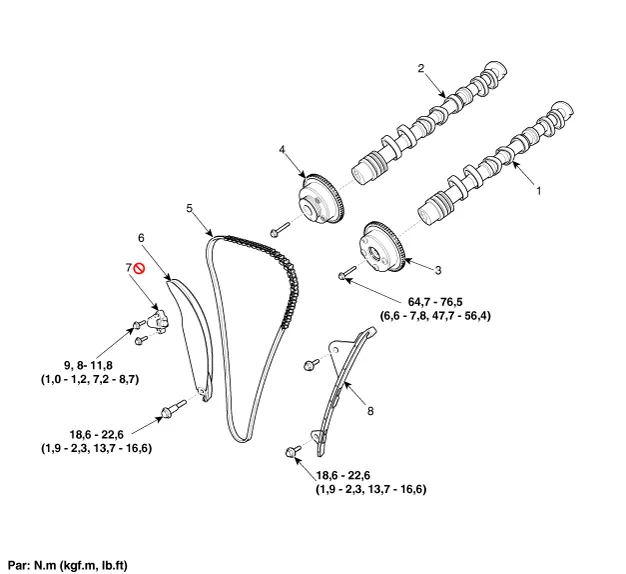
| 1. Intake
camshaft 2. Exhaust camshaft 3. Intake CVVT assembly 4. Exhaust CVVT assembly |
5. Timing
chain 6. Timing chain tensioner arm 7. Timing chain tensioner 8. Timing chain guide |
Repair procedures
| Removal |
| 1. |
Remove the cylinder head cover. (Refer to Cylinder Head Assembly - "Cylinder Head Cover") |
| 2. |
Set No.1 cylinder to TDC (Top dead center) on compression stroke.
|

| 3. |
Remove the timing chain cover. (Refer to Timing System - "Timing Chain Cover") |
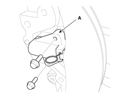
| 4. |
Remove the timing chain tensioner (A).
|
| 5. |
Remove the timing chain tensioner arm (A).
|
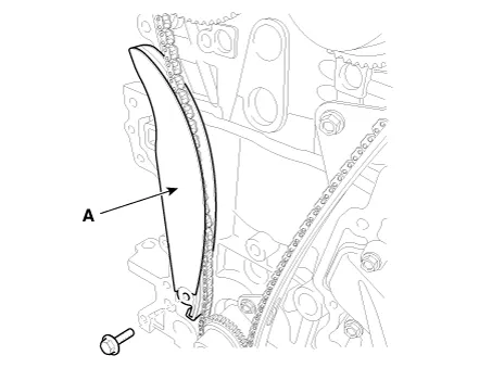
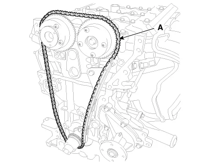
| 6. |
Remove the timing chain (A).
|
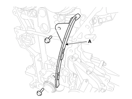
| 7. |
Remove the timing chain guide (A).
|
| Inspection |
Sprockets, Chain Tensioner, Chain Guide, Chain Tensioner Arm
| 1. |
Check the CVVT sprocket and crankshaft sprocket for abnormal wear, cracks, or damage. Replace if necessary. |
| 2. |
Inspect the tensioner arm and chain guide for abnormal wear, cracks, or damage. Replace if necessary. |
| Installation |
| 1. |
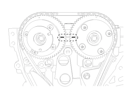
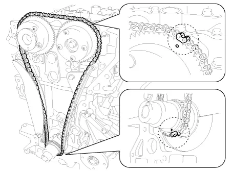
The TDC marks of the intake and exhaust CVVT sprockets are slightly turned from the TDC position as shown when the timing chain is removed.
|
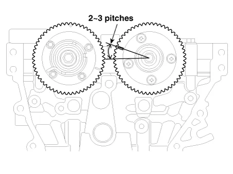
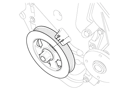
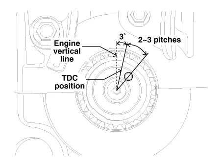
| 2. |
Turn the crankshaft clockwise (about 2-3 pitches) from the TDC position (the dowel pin (A) of crankshaft is about 3° with the engine vertical line) as rotation of the intake CVVT sprocket from the TDC position.
|
| 3. |
Install the timing chain guide (A).
|
| 4. |
Install the timing chain tensioner arm (A).
|
| 5. |
Install the timing chain. Crankshaft sprocket (A) → Timing chain guide (B) → Intake CVVT sprocket (C) → Exhaust CVVT sprocket (D)
|
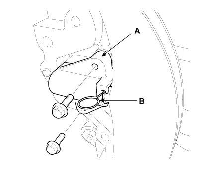
| 6. |
Install the timing chain auto tensioner (A) and remove the stopper pin (B).
|
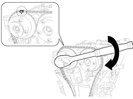
| 7. |
After rotating crankshaft 2 revolutions in regular direction (clockwise viewed from front), confirm that the TDC marks on the intake and exhaust CVVT sprockets are aligned with the top surface of cylinder head.
|
| 8. |
Install the other parts reverse order of removal. |
|
Components and components location Components 1. Timing chain cover 2. Service plug bolt & gasket Repair procedures Removal Engine removal is not required for this procedure.
Service data Service Data Ignition System Ignition Coil Item Specification Primary Coil Resistance (Ω) 0.
Other information:
Kia Optima DL3 2019-2026 Service and Repair Manual: Vanity Lamp
Repair procedures Removal When removing with a flat-tip screwdriver or remover, wrap protective tape around the tools to prevent damage to components. 1.
Kia Optima DL3 2019-2026 Service and Repair Manual: Wiper Motor
Schematic diagrams Connector and Terminal Function Pin Function 1 Ground (-) 2 Parking 3 Power (+) 4 Low 5 High Repair procedures Remova
Categories
- Manuals Home
- Kia Optima Owners Manual
- Kia Optima Service Manual
- Rear Brake Disc
- Timing Chain
- Body Electrical System
- New on site
- Most important about car
