Kia Optima DL3: Seat Electrical / Heated Seats Only
Components and components location
| Components |
| Front Seat Heater |
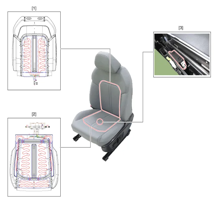
| 1. Front seat back heater 2. Front seat cushion heater |
3. Front seat heater unit / ventilation
unit |
| Rear Seat Heater |

| 1. Rear seat heater unit 2. Rear seat back heater |
3. Rear seat cushion heater
|
Schematic diagrams
| Connector and Terminal Function |
Front Seat Heater Unit
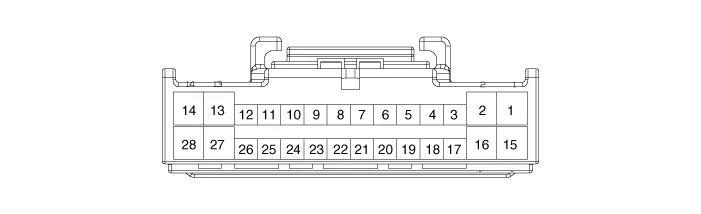
|
Pin |
Function |
Pin |
Function |
|
1 |
Battery (+) |
15 |
Battery (+) |
|
2 |
Driver heater power (+) |
16 |
Passenger heater power (+) |
|
3 |
IGN1 |
17 |
IGN2 |
|
4 |
CAN (Low) |
18 |
- |
|
5 |
CAN (High) |
19 |
Detent |
|
6 |
- |
20 |
Illumination (-) |
|
7 |
Driver heater indicator (High) |
21 |
Passenger heater indicator (High) |
|
8 |
Driver heater indicator (Mid) |
22 |
Passenger heater indicator (Mid) |
|
9 |
Driver heater indicator (Low) |
23 |
Passenger heater indicator (Low) |
|
10 |
Driver heater switch |
24 |
Passenger heater switch |
|
11 |
Driver heater NTC (+) |
25 |
Passenger heater NTC (+) |
|
12 |
Driver heater NTC (-) |
26 |
Passenger heater NTC (-) |
|
13 |
Driver heater ground (-) |
27 |
Passenger heater ground (-) |
|
14 |
Ground |
28 |
Ground |
Front Seat Heater Unit (Ventilation seat unit)
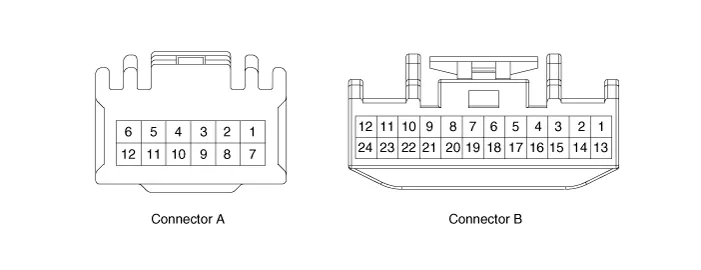
|
Pin |
Function |
|
|
Connector A |
Connector B |
|
|
1 |
Driver heater ground (-) |
Driver blower speed (+) |
|
2 |
Passenger heater ground (-) |
- |
|
3 |
Driver cushion heater power (+) |
CAN (Low) |
|
4 |
Driver back heater power (+) |
CAN (High) |
|
5 |
Passenger cushion heater power (+) |
- |
|
6 |
Passenger back heater power (+) |
LIN |
|
7 |
ECU (Ground) |
Detent |
|
8 |
ECU (Ground) |
IGN1 |
|
9 |
|
Driver blower speed |
|
10 |
Passenger blower speed |
|
|
11 |
Illumination (-) |
|
|
12 |
Driver NTC (-) |
|
|
13 |
Passenger NTC (-) |
|
|
14 |
- |
|
|
15 |
- |
|
|
16 |
- |
|
|
17 |
- |
|
|
18 |
- |
|
|
19 |
- |
|
|
20 |
IGN2 |
|
|
21 |
- |
|
|
22 |
Driver NTC (+) |
|
|
23 |
Passenger NTC (+) |
|
|
24 |
- |
|
Rear Seat Heater Unit
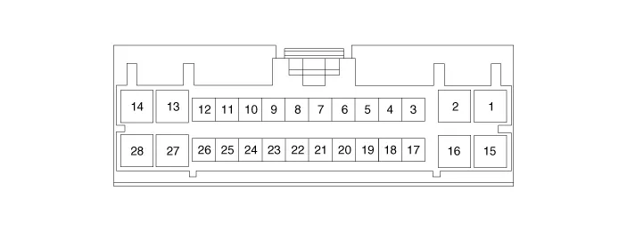
|
Pin |
Function |
Pin |
Function |
|
1 |
Battery (+) |
15 |
Battery (+) |
|
2 |
Heater power (+)_LH |
16 |
Heater power (+)_RH |
|
3 |
IGN1 |
17 |
IGN2 |
|
4 |
CAN (Low) |
18 |
- |
|
5 |
CAN (High) |
19 |
- |
|
6 |
- |
20 |
- |
|
7 |
Heater indicator (High)_LH |
21 |
Heater indicator (High)_RH |
|
8 |
- |
22 |
- |
|
9 |
Heater indicator (Low)_LH |
23 |
Heater indicator (Low)_RH |
|
10 |
Heater switch_LH |
24 |
Heater switch_RH |
|
11 |
Heater NTC (+)_LH |
25 |
Heater NTC (+)_RH |
|
12 |
Heater NTC (-)_LH |
26 |
Heater NTC (-)_RH |
|
13 |
Heater ground (-)_LH |
27 |
Heater ground (-)_RH |
|
14 |
Ground |
28 |
Ground |
Repair procedures
| Inspection |
Driver/Passenger Seat Heater
| 1. |
Check for continuity and measure the resistance between terminals.
|
|||||||||||||||||||||||||||||||||||||
| 2. |
Operate the seat heater after connecting the connector, and then check the thermostat by measuring the temperature of seat surface.
|
||||||||||
Rear Seat Heater
| 1. |
Check for continuity and measure the resistance between terminals.
|
| 2. |
Operate the seat heater after connecting the connector, and then check the thermostat by measuring the temperature of seat surface.
|
||||||||
| Removal |
Front Seat Heater Unit
| 1. |
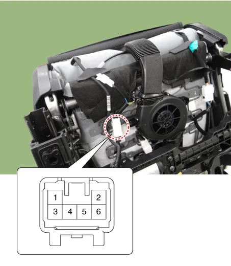
Remove the passenger seat assembly. (Refer to Body - "Front Seat assembly") |
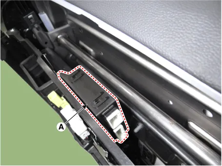
| 2. |
Disconnect the seat heater unit connector (A).
|
| 3. |
Remove the front seat heater unit (A) by loosening the screws.
|
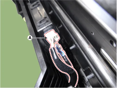
Rear Seat Heater Unit
| 1. |
Disconnect the negative battery terminal. |
| 2. |
Remove the rear seat cushion assembly. (Refer to Body - "Rear Seat Assembly") |
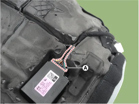
| 3. |
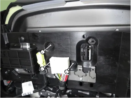
Disconnect the rear seat heater unit connector (A).
|
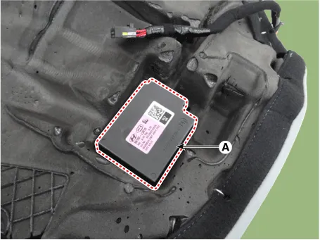
| 4. |
Remove the rear seat heater unit (A).
|
| Installation |
| 1. |
Install in the reverse order of removal. |
Schematic diagrams Connector and Terminal Function [Front Seat] [Ventilation+Heater Type / Non-Heater Type] Pin Function Pin Function Ventilation+Heater Type Non-Heater Type Ventilation+Heater Type Non-Heater Type 1 IGN1 - 9 Illumination (+) 2 - - 10 - 3 - - 11 Illumination (-) 4 Ground - 12 - 5 - 13 Steering heater mode - 6 - 14 Steering heater indicator - 7 LIN - 15 Driver mode switch (CW) 8 Ground 16 Driver mode switch (CCW) [Heater Type] Pin Function Pin Function 1 Heater indicator (High)_RH 13 Heater mode_RH 2 Heater indicator (Mid)_RH 14 - 3 Heater indicator (Low)_RH 15 - 4 - 16 Ground 5 Driver mode switch (CW) 17 - 6 Driver mode switch (CCW) 18 Illumination (-) 7 Steering heater mode 19 - 8 Steering heater indicator 20 Illumination (+) 9 Heater mode_LH 21 - 10 Heater indicator (High)_LH 22 - 11 Heater indicator (Mid)_LH 23 - 12 Heater indicator (Low)_LH 24 - [Rear Seat] [Safety Type] Pin Function Pin Function 1 Ground (Illumination -) 5 Ground 2 Door lock switch 6 Door lock indicator 3 Door unlock switch 7 Safety power window 4 Battery + (Illumination +) 8 - [Manual Type] Pin Function Pin Function 1 Ground 7 Driver window down 2 Seat warmer (High) 8 Window enble 3 Window down motor 9 Ground (Illumination -) 4 Seat warmer (Low) 10 Driver window up 5 Window up motor 11 Battery + (Illumination +) 6 Seat warmer switch 12 Battery (+) Repair procedures Inspection [Front Seat] 1.
Other information:
Kia Optima DL3 2019-2026 Service and Repair Manual: Mood Lamp Unit
Schematic diagrams Connector and Terminal function Repair procedures Removal When removing with a flat-tip screwdriver or remover, wrap protective tape around the tools to prevent damage to components.
Kia Optima DL3 2019-2026 Service and Repair Manual: Smart Key Diagnostic
Repair procedures Inspection 1. In the body electrical system, failure can be quickly diagnosed by using the vehicle diagnostic system (KDS). The diagnostic system (KDS) provides the following information. (1) Self diagnosis : Checking failure and code number (DTC).
Categories
- Manuals Home
- Kia Optima Owners Manual
- Kia Optima Service Manual
- Charging System
- Timing Chain
- Battery
- New on site
- Most important about car
