Kia Optima DL3: Your vehicle at a glance / Instrument panel overview
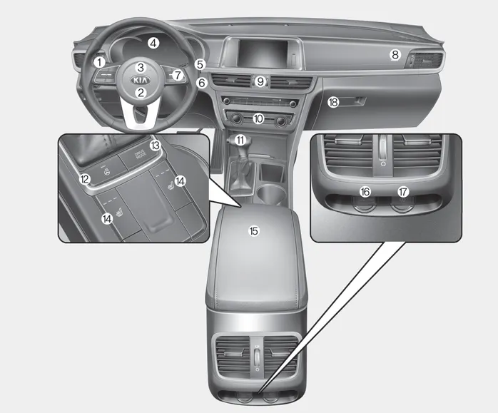
1. Light control/Turn signals
2, Driver’s front air bag
3. Horn
4. Instrument cluster
5. Wiper and washer control lever
6. Ignition switch
Engine start/stop button
7. Cruise control
8. Passenger’s front air bag
9. Hazard warning flasher
10. Manual climate control system
Automatic climate control system
11. Shift lever A/T
12. Heated steering wheel button
13. Drive mode button
14. Seat warmer
15. Center console storage box
16. Power outlet
17. USB charger
18. Glove box
1. Inside door handle 2. Driver position memory button 3. Power window switch 4. Central door lock switch 5. Power window lock button 6. Outside rearview mirror control 7.
■ THETA 2.4L - GDI 1. Engine coolant reservoir 2. Engine oil filler cap 3. Brake fluid reservoir 4. Air cleaner 5. Fuse box 6. Negative battery terminal 7.
Other information:
Kia Optima DL3 2019-2026 Service and Repair Manual: Heating, Ventilation and Air Conditioning
Service data Service Data Air Conditioner ltem Specification Compressor Type 6SAS14 Oil type & Capacity ND-OIL 12 80 ± 10 cc (2.82 ± 0.
Kia Optima DL3 2019-2026 Service and Repair Manual: Ambient Temperature Sensor
Description and operation Description The ambient temperature sensor is located at the front of the condenser and detects ambient air temperature. It is a negative type thermistor; resistance will increase with lower temperature, and decrease with higher temperature.
Categories
- Manuals Home
- Kia Optima Owners Manual
- Kia Optima Service Manual
- Lift And Support Points
- Headlamps
- Timing Chain
- New on site
- Most important about car
