
Kia Optima DL3: Seat Electrical / Power Seat Control Switch
Repair procedures
| Removal |
| 1. |
Remove the front seat shield outer cover. (Refer to Body - "Front Seat Shield Outer Cover") |
| 2. |
Remove the power seat control switch (A) by loosening the mounting screws.
|
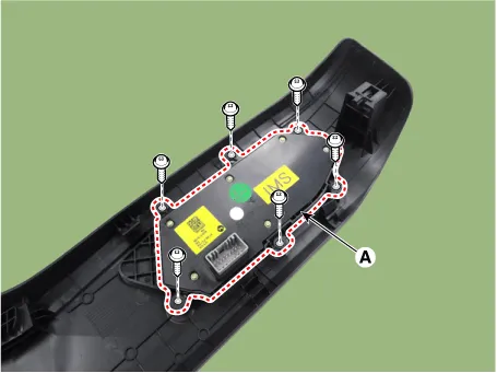
| Installation |
| 1. |
Install in the reverse order of removal. |
Repair procedures Inspection 1. Remove the front seat back. (Refer to Body - "Front Seat Back Cover") 2.
Components and components location Components 1. Lumbar support motor 2. Reclining motor 3. Front height motor 4.
Other information:
Kia Optima DL3 2019-2026 Service and Repair Manual: Washer Motor
Repair procedures Inspection Washer Motor 1. With the washer motor connected to the reservoir tank, fill the reservoir tank with water. Before filling the reservoir tank with water, check the filter for foreign mat
Kia Optima DL3 2019-2026 Service and Repair Manual: Ambient Temperature Sensor
Description and operation Description The ambient temperature sensor is located at the front of the condenser and detects ambient air temperature. It is a negative type thermistor; resistance will increase with lower temperature, and decrease with higher temperature.
Categories
- Manuals Home
- Kia Optima Owners Manual
- Kia Optima Service Manual
- Charging System
- Body Electrical System
- Cooling System
- New on site
- Most important about car
