Kia Optima DL3: Audio/AVN System / A/V Navigation
Components and components location
| Components |
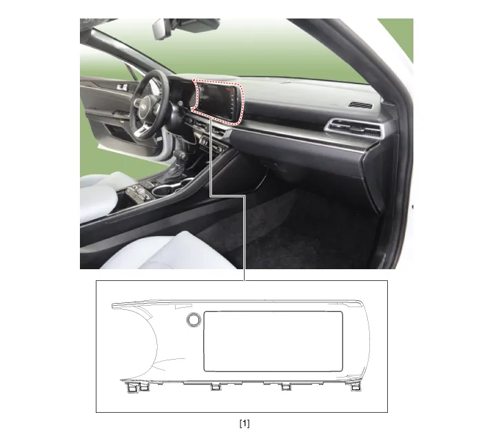
| 1. AVN head unit |
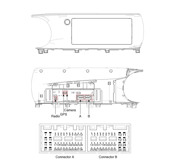
Schematic diagrams
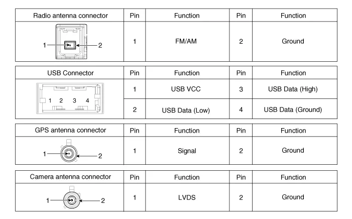
| Connector and Terminal Function |
AVN 5.0
| [A Type] |

| [B Type] |
|
Pin |
Function |
||
|
Connector A |
Connector B |
||
|
External Amplifier |
Internal Amplifier |
||
|
1 |
- |
Left rear door speaker (+) |
- |
|
2 |
- |
Left rear door speaker (-) |
MIC1 (+) |
|
3 |
Amplifier navigation voice (+) |
- |
- |
|
4 |
Amplifier_SPDIF (High) |
- |
- |
|
5 |
- |
- |
|
|
6 |
CVBS Type : Camera power / LVDS Type : - |
Illumination (+) |
|
|
7 |
CVBS Type : Camera video / LVDS Type : - |
MM-CAN (High) |
|
|
8 |
- |
- |
|
|
9 |
- |
- |
|
|
10 |
- |
Battery (+) |
|
|
11 |
- (USB Detect) |
Battery (+) |
|
|
12 |
Steering wheel key |
Ground |
|
|
13 |
- |
Left front door speaker (+) |
Ground |
|
14 |
- |
Left front door speaker (-) |
- |
|
15 |
- |
Right front door speaker (-) |
MIC1 (-) |
|
16 |
- |
Right front door speaker (+) |
- |
|
17 |
Amplifier navigation voice (-) |
- |
- |
|
18 |
Amplifier SPDIF (Low) |
- |
- |
|
19 |
Amplifier SPDIF (Ground) |
- |
Illumination (-) |
|
20 |
CVBS Type : Camera power ground / LVDS Type : - |
MM-CAN (Low) |
|
|
21 |
CVBS Type : Camera video ground / LVDS Type : - |
- |
|
|
22 |
- |
ACC |
|
|
23 |
- |
- |
|
|
24 |
- |
- |
|
|
25 |
- |
- |
|
|
26 |
Steering wheel key ground |
- |
|
|
27 |
- |
Right rear door speaker (-) |
- |
|
28 |
- |
Right rear door speaker (+) |
- |
|
29 |
- |
- |
|
|
30 |
- |
- |
|
|
31 |
- |
- |
|
|
32 |
RVM : - / SVM : Ground |
- |
|
|
33 |
CVBS Type : Camera shield ground / LVDS Type : - |
IGN1 |
|
|
34 |
- |
- |
|
|
35 |
- |
- |
|
|
36 |
- |
|
|
|
37 |
- |
||
|
38 |
Vehicle speed |
||
Repair procedures
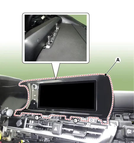
| Removal |
|

| 1. |
Disconnect the negative battery terminal. |
| 2. |
Remove the crash pad garnish [RH]. (Refer to Body - "Crash Pad Garnish") |
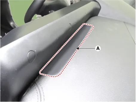
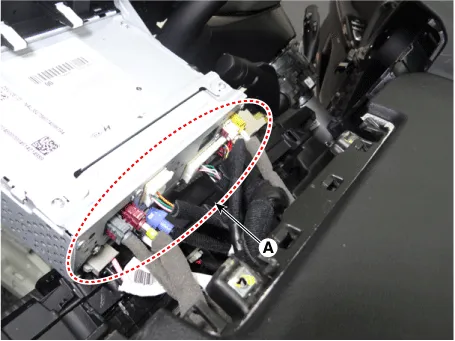
| 3. |
Remove the AVN head unit.
|
| Installation |
| 1. |
Install in the reverse order of removal. |
Components and components location Component Location 1. Audio head unit/AVN head unit 2. Tweeter speaker 3. Center speaker 4.
Components and components location Components 1. Audio head unit 2. Display audio head unit Schematic diagrams Connector and Terminal Function Audio 4.
Other information:
Kia Optima DL3 2019-2026 Service and Repair Manual: Ventilated and Heated Seat
Schematic diagrams Connector and Terminal Function Pin Function Connector A Connector B 1 Driver heater ground (-) Driver blower speed (+) 2 Passenger heater ground (-) - 3
Kia Optima DL3 2019-2026 Service and Repair Manual: Smart Key
Repair procedures Adjustment Smart Key Code Saving 1. Connect the VCI II in driver side crash pad lower panel, turn the power on KDS. 2. Select the vehicle model and then do "Smart key code saving".
Categories
- Manuals Home
- Kia Optima Owners Manual
- Kia Optima Service Manual
- Heating, Ventilation and Air Conditioning
- Automatic Transaxle System
- Motor Driven Power Steering
- New on site
- Most important about car
