Kia Optima DL3: Rear Corner Radar System / BCW & RCCA Indicator
Repair procedures
| Inspection |
| 1. |
Remove the front door trim. (Refer to Body - "Frond Door Trim") |
| 2. |
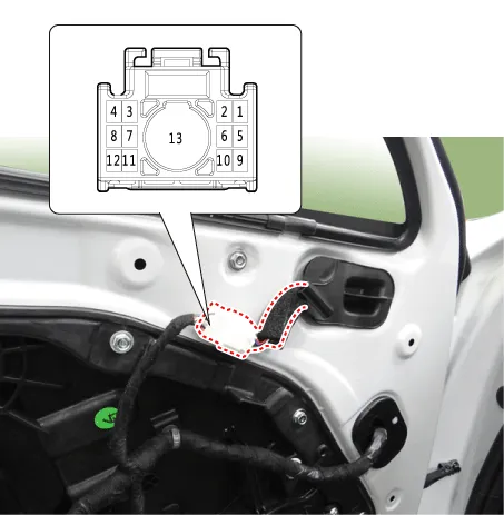
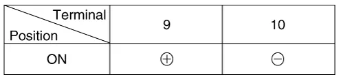
Check that the mirror operates properly as shown in the table below.
|
| Removal |
| 1. |
Disconnect the negative battery terminal. |
| 2. |
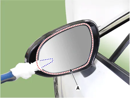
Remove the mirror (A).
|

| 3. |
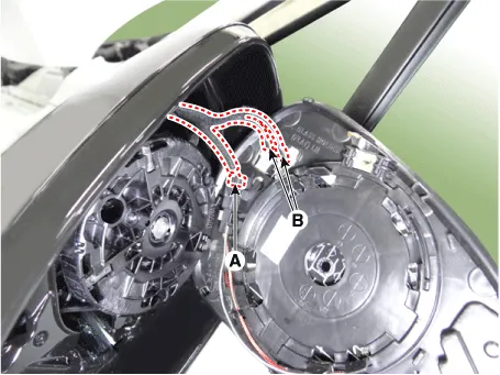
Disconnect the heater connectors (A) and BCW indicator connector (B).
|
| Installation |
| 1. |
Install in the reverse order of removal. |
Specifications Specifications Item Specification Rated voltage 12 V Operating voltage 9 - 16 V Max.
Description and operation Cruise Control The cruise control system is engaged by the cruise "ON/OFF" main switch located on the right-hand side of steering wheel column.
Other information:
Kia Optima DL3 2019-2026 Service and Repair Manual: Integrated Memory Seat (IMS) Switch
Schematic diagrams Connector and Terminal Function Repair procedures Removal When prying with a flat-tip screwdriver or use a prying trim tool, wrap it with protective tape, and apply protective tape around the related parts, to prevent dam
Kia Optima DL3 2019-2026 Service and Repair Manual: Power Windows
Components and components location Component Location 1. Power window main switch 2. Rear window main switch 3. Front power window motor 4. Rear power window motor Description and operation Description Power Window Safety Function When the driver or passenger p
Categories
- Manuals Home
- Kia Optima Owners Manual
- Kia Optima Service Manual
- Rear Brake Disc
- Heating, Ventilation and Air Conditioning
- Steering System
- New on site
- Most important about car
