Kia Optima DL3: Rear Corner Radar System / Rear Corner Radar Unit
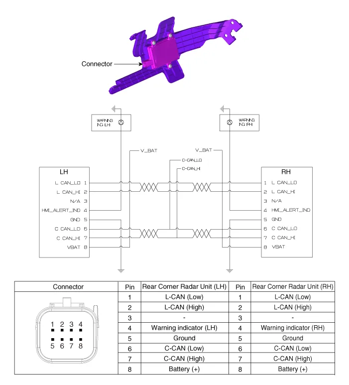
Specifications
| Specifications |
|
Item |
Specification |
|
Rated voltage |
12 V |
|
Operating voltage |
9 - 16 V |
|
Max. distance |
70 m |
|
Quantity |
2 units (Master 1 unit, Slave 1 unit) |
|
Function |
BCA, SEA, RCCA |
Schematic diagrams
| Connector and Terminal Function |
Repair procedures
| Inspection |
| 1. |
In the body electrical system, failure can be quickly diagnosed by using the vehicle diagnostic system (KDS). The diagnostic system (KDS) provides the following information.
|
| Removal |
lf replacement of the rear corner radar unit bracket or extension wire is required, replace the defective part only with a new one. |

| 1. |
Disconnect the negative (-) battery terminal. |
| 2. |
Remove the rear bumper assembly. (Refer to Body - "Rear Bumper Assembly") |
| 3. |
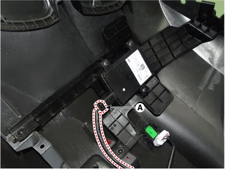
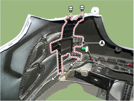
Disconnect the connector (A) from the rear corner radar unit.
|
| 4. |
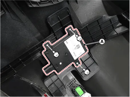
Remove the rear corner radar unit (A) by loosening the screws.
|
| Installation |
| 1. |
Install in the reverse order of removal.
|
| Adjustment |
To correctly sense vehicles on the neighboring lanes using the radar, the direction of the sensor and the direction of the vehicle must be aligned.
This is the rear corner radar unit alignment. If this alignment is not performed as in illustration below, it may cause degradation of detection performance and false alarms.
In particular, vehicles with damaged rear bumper from accident and vehicles that replaced rear corner radar unit must carry out this alignment procedure.

| 1. |
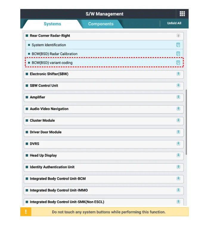
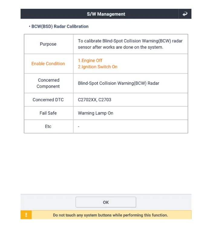
Perform the radar calibration procedure using the KDS. |
| 2. |
Select "BCW(BSD) Radar Calibration" procedure in 'Rear Corner Radar' system. |
| 3. |
Perform the "BSD Radar Calibration" procedure as indicated on KDS screen.
|

Components and components location Components 1. Cluster (User setting menu) 2. Rear corner radar 3. Rear corner radar indicator Description and operation Description System Interface System Function • Blind-Spot Collision Warning (BCW) This system uses an audible warning and BCW signal on the mirror when sensing a vehicle in the blind spot area or when the vehicle is approaching at a high speed.
Repair procedures Inspection 1. Remove the front door trim. (Refer to Body - "Frond Door Trim") 2.
Other information:
Kia Optima DL3 2019-2026 Service and Repair Manual: Rheostat
Schematic diagrams Connector and Terminal Function Repair procedures Removal 1. Disconnect the negative battery terminal. 2. Remove the crash pad lower panel. (Refer to Body - "Crash Pad Lower Panel") 3.
Kia Optima DL3 2019-2026 Service and Repair Manual: Smart Key Diagnostic
Repair procedures Inspection 1. In the body electrical system, failure can be quickly diagnosed by using the vehicle diagnostic system (KDS). The diagnostic system (KDS) provides the following information. (1) Self diagnosis : Checking failure and code number (DTC).
Categories
- Manuals Home
- Kia Optima Owners Manual
- Kia Optima Service Manual
- Brake System
- Engine Control / Fuel System
- Body (Interior and Exterior)
- New on site
- Most important about car
