Kia Optima DL3: Integrated Memory Seat (IMS) / Integrated Memory Seat (IMS) Switch
Schematic diagrams
| Connector and Terminal Function |
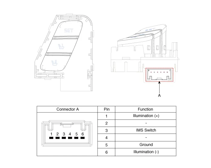
Repair procedures
| Removal |
When prying with a flat-tip screwdriver or use a prying trim tool, wrap it with protective tape, and apply protective tape around the related parts, to prevent damage. |

| 1. |
Disconnect the negative battery terminal. |
| 2. |
Remove the front driver door trim. (Refer to Body - "Front Door Trim") |
| 3. |
Disconnect the IMS switch connector (A).
|
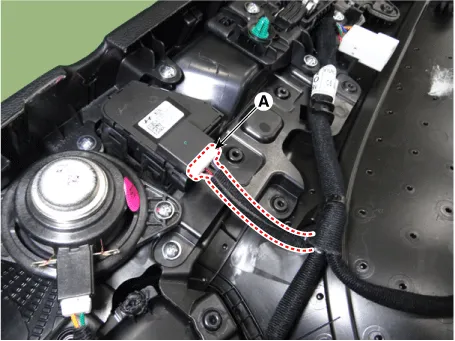
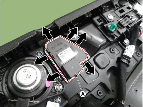
| 4. |
Remove the IMS switch (A) by pushing the hooks in the direction of arrow.
|
| Installation |
| 1. |
Install in the reverse order of removal. |
| Inspection |
| 1. |
Disconnect the negative battery terminal. |
| 2. |
Remove the front driver door trim. (Refer to Body - "Front Door Trim") |
| 3. |
Disconnect the IMS switch connector (A).
|
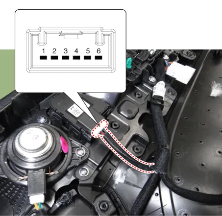
| 4. |
When each switch is pressed, check the electricity flow between integrated memory seat switch connector and ground.
|
Specifications Specifications Item Specifications Rated voltage DC 12 V Operating voltage DC 9 - 16 V Operating temperature range -22 to 167°F (-30 to 75°C) Dark current Max.
Components and components location Component Location 1. Integrated Body Control Unit (IBU) Schematic diagrams Connector and Terminal Function [Non-Smart key] Pin Function Connector A Connector B 1 - Front washer switch (Output) 2 Rear seat belt indicator_Left (Output) - 3 - Key solenoid (Output) 4 - Key in switch (Input) 5 - Key inter lock switch (Input) / 'P' : Position switch 6 Rear seat belt indicator_Center (Output) Wiper parking switch (Input) 7 - - 8 Rear seat belt indicator_Right (Output) Brake switch (Input) 9 - - 10 Headlamp high switch (Input) Front wiper volume switch (Input) 11 - Key hole illumination (Output) 12 - LIN4 (Safety ECU) 13 Rear view switch (Input) PAS Option (Input) 14 - - 15 RPAS Power (Output) B-CAN (Low) 16 FRAS Power (Output) B-CAN (High) 17 PAS/RPAS Power (Input) - 18 - Ground (Power) 19 - - 20 Ground (ECU) Immobilizer power (Output) 21 - Immobilizer ground (Output) 22 K-Line_Immobilizer Start inhibit relay 23 - PAS/RPAS Switch indicator (Output) 24 - Front wiper switch (Input) 25 Sunroof status (Input) - 26 PAS/RPAS Switch (Input) Multifunction switch ground (Input) 27 ATM Solenoid (Output) Wiper power relay (Output) 28 - Auto light sensor ground (Output) 29 LIN2 (ROA) Auto light sensor signal (Input) 30 LIN1 (PDW-F or PDW-R) Auto light sensor power (Output) 31 Door unlock signal (For IFU) EMS (Output) - 32 Light switch (Input) Front wiper high relay (Output) 33 Fog switch (Input) Front wiper low relay (Output) 34 IGN2 (Input) Front wiper low backup switch (Input) 35 IGN1 (Input) P-CAN (Low) 36 ACC (Input) P-CAN (High) 37 Battery + (ECU) 38 Battery + (Power) 39 - 40 Front heated nozzle (Output) [Smart key] Pin Function Connector A Connector B Connector C Connector D 1 - Front washer switch (Output) - Driver outside handle switch (Input) 2 Rear seat belt indicator_Left (Output) - ESCL Enable (Output) Assist outside handle switch (Input) 3 - - ESCL - (Output) - 4 - - - - 5 External buzzer (Output) - - RPM (Input) 6 Rear seat belt indicator_Center (Output) Wiper parking switch (Input) - SSB symbol illumination (+) (Output) 7 Puddle pocket lamp (Output) - ESCL Unlock switch (Input) ACC relay (Output) 8 Rear seat belt indicator_Right (Output) Brake switch (Input) - IGN1 relay (Output) 9 - - - IGN2 relay (Output) 10 Headlamp high switch (Input) Front wiper volume switch (Input) ESCL + (Output) Starter relay (Output) 11 - - Assist outside handle antenna (+) (Output) 12 - LIN4 (Safety ECU) Interior antenna 2 (+) (Output) 13 Rear view switch (Input) PAS Option (Input) Trunk interior antenna 3 (+) (Output) 14 - - Interior antenna 1 (+) (Output) 15 RPAS Power (Output) B-CAN (Low) Bumper antenna (+) (Output) 16 FRAS Power (Output) B-CAN (High) Driver outside handle antenna (+) (Output) 17 PAS/RPAS Power (Input) - - 18 - Ground (Power) - 19 - - - 20 Ground (ECU) Immobilizer power (Output) - 21 - Immobilizer ground (Output) SSB switch 1 (Input) 22 K-Line_Immobilizer - SSB switch 2 (Input) 23 - PAS/RPAS Switch indicator (Output) Clutch IGN lock switch 24 - Front wiper switch (Input) ESCL COM 25 Sunroof status (Input) - Wheel speed sensor (Input) 26 PAS/RPAS Switch (Input) Multifunction switch ground (Input) - 27 ATM Solenoid (Output) Wiper power relay (Output) - 28 LIN3 (Rain sensor) Auto light sensor ground (Output) - 29 LIN2 (ROA) Auto light sensor signal (Input) - 30 LIN1 (PDW-F or PDW-R) Auto light sensor power (Output) Start feed back (Input) 31 Door unlock signal (For IFU) EMS (Output) - Assist outside handle antenna (-) (Output) 32 Light switch (Input) Front wiper high relay (Output) Interior antenna 2 (-) (Output) 33 Fog switch (Input) Front wiper low relay (Output) Trunk interior antenna 3 (-) (Output) 34 IGN2 (Input) Front wiper low backup switch (Input) Interior antenna 1 (-) (Output) 35 IGN1 (Input) P-CAN (Low) Bumper antenna (-) (Output) 36 ACC (Input) P-CAN (High) Driver outside handle antenna (-) (Output) 37 Battery + (ECU) - 38 Battery + (Power) - 39 - - 40 Front heated nozzle (Output) 'P' Position (input) Description and operation Description Integrated Body Control Unit (IBU) Integrated body control unit has integrated several functions including body control module (IBU), smart key unit (SMK), and tire pressure monitoring system (TPMS).
Other information:
Kia Optima DL3 2019-2026 Service and Repair Manual: Washer Motor
Repair procedures Inspection Washer Motor 1. With the washer motor connected to the reservoir tank, fill the reservoir tank with water. Before filling the reservoir tank with water, check the filter for foreign mat
Kia Optima DL3 2019-2026 Service and Repair Manual: Cluster Ionizer
Components and components location Components Location 1. Condenser Description and operation Description The cluster ionizer makes disinfection and decomposition of bad smell from the air-conditioner or inflow air.
Categories
- Manuals Home
- Kia Optima Owners Manual
- Kia Optima Service Manual
- Engine Mechanical System
- Heating, Ventilation and Air Conditioning
- Automatic Transaxle System
- New on site
- Most important about car
