Kia Optima DL3: Cooling System / Cooling Fan
Components and components location
| Components |
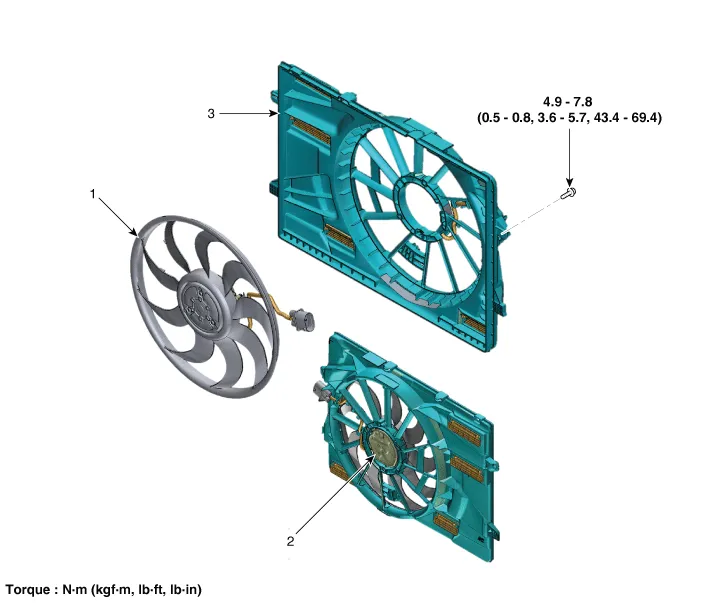
| 1. Cooling fan 2. Cooling fan motor |
3. Cooling fan shroud |
Specifications
| Specifications |
|
Item |
Specification |
|
Fan type |
PULLER |
|
Fan speed control |
Resisor |
|
Air flow rate (㎥/h) |
1,950 - 8% min. |
|
Fan speed (rpm) |
1,650 ± 8% |
|
Current (A) |
11.7 + 10% max. |
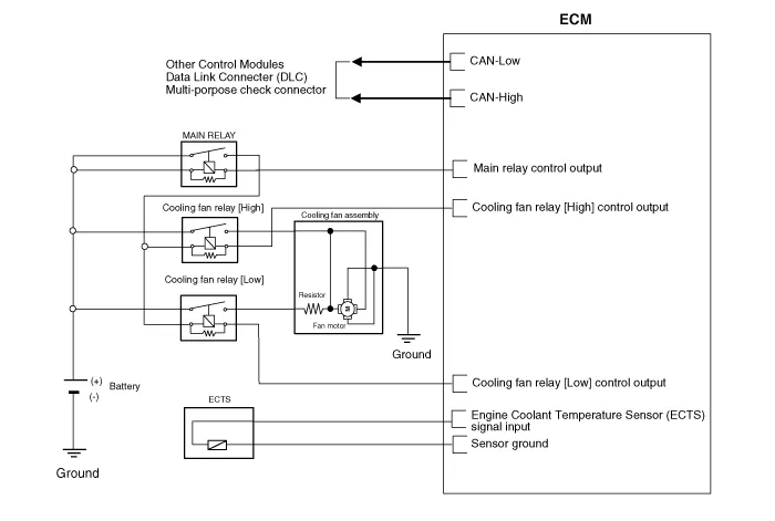
Schematic diagrams
| Circuit Diagram |
Repair procedures
| Removal and Installation |
Cooling fan assembly
| 1. |
Disconnect the battery negative terminal. |
| 2. |
Remove the air duct. (Refer to Intake And Exhaust System - "Air Cleaner") |
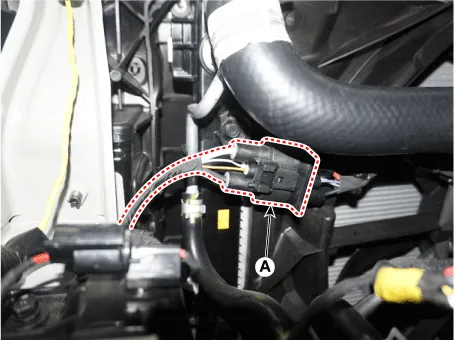
| 3. |
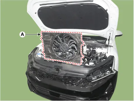
Disconnect the wiring harness connector (A).
|
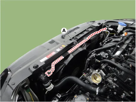
| 4. |
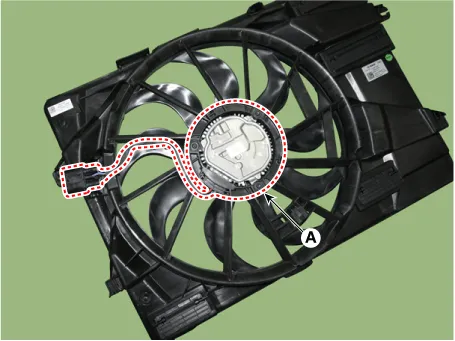
Separate the degassing hose (A) from cooling fan.
|

| 5. |
Remove the cooling fan assembly (A) from radiator.
|
| 6. |
Install in the reverse order of removal. |
| Disassembly |
| 1. |
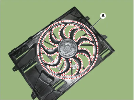
Remove the cooling fan and cooling fan motor (A) from the cooling fan shroud.
|
| 2. |
Assemble in the reverse order of disassembly. |
| Inspection |
| 1. |
Turn ignition switch "OFF" and connect the KDS to the Data Link Connector. |
| 2. |
With the gear shift in P (Park) position and ignistion switch "ON" (LED of the Power button illuminates in Red), select the "force drive" function. |
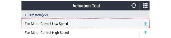
| 3. |
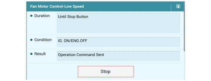
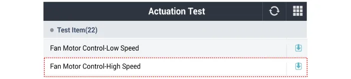
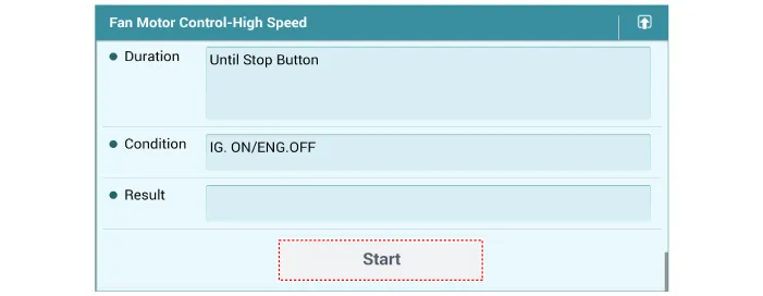
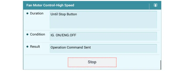
Force drive the cooling fan motor.
[Fan motor low speed]
[Fan motor high speed]
|

Repair procedures Removal and Installation 1. Remove the reservoir tank. (1) Disconnect the degassing hose (A).
Components and components location Components 1. Radiator 2. Radiator upper mounting bracket 3. Radiator upper hose 4.
Other information:
Kia Optima DL3 2019-2026 Service and Repair Manual: Cluster Ionizer
Components and components location Components Location 1. Condenser Description and operation Description The cluster ionizer makes disinfection and decomposition of bad smell from the air-conditioner or inflow air.
Kia Optima DL3 2019-2026 Service and Repair Manual: Power Mosfet
Description and operation Description It is installed to the DATC and adjusts the fan rpm by precisely controlling the voltage applied to the blower motor. Repair procedures Inspection 1. Turn the ignition switch ON.
Categories
- Manuals Home
- Kia Optima Owners Manual
- Kia Optima Service Manual
- Automatic Transaxle System
- Body (Interior and Exterior)
- Cooling System
- New on site
- Most important about car
