Kia Optima DL3: Cooling System / Radiator
Components and components location
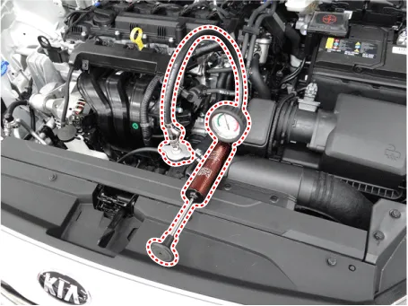
| Components |
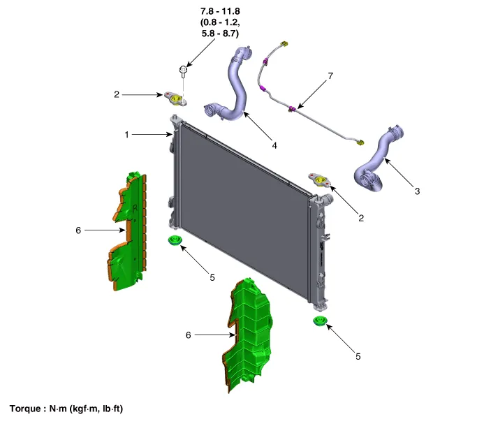
| 1. Radiator 2. Radiator upper mounting bracket 3. Radiator upper hose 4. Radiator lower hose |
5. Radiator lower mounting insulator
6. Radiator air guard 7. Degassing hose and pipe |
Repair procedures
| Removal and Installation |
| 1. |
Remove the cooling fan. (Refer to Cooling System - "Cooling Fan") |
| 2. |
Drain engine coolant by loosening the drain plug. (Refer to Cooling System - "Coolant") |
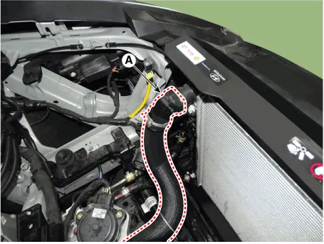
| 3. |
Disconnect the radiator upper hose (A).
|
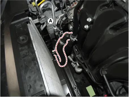
| 4. |
Disconnect the radiator lower hose (A).
|
| 5. |
Remove the front bumper assembly. (Refer to Body (Interior and Exterior) - "Front Bumper Assembly") |
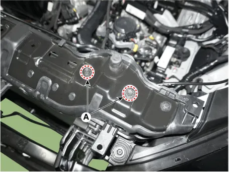
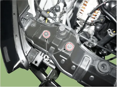
| 6. |
Remove the radiator upper mounting bolts (A) and then remove the radiator upper mounting brackets.
[LH]
[RH]
|
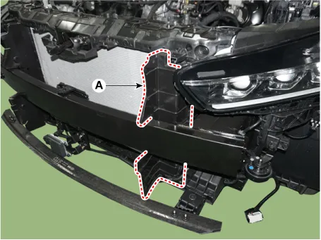
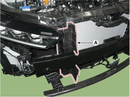
| 7. |
Remove the radiator air guard (A). [LH]
[RH]
|
| 8. |
Separate the condenser from the radiator. |
| 9. |
Pull the raditor (A) upward and remove it from engine room.
|

| 10. |
Install in the reverse order of removal. |
| 11. |
Fill with engine coolant. (Refer to Cooling System - "Coolant") |
| 12. |
Start engine and check for leaks. |
| 13. |
Recheck engine coolant level. |
| Inspection |
Reservoir Cap Testing
| 1. |
Install the pressure cap and pressure tester on a SST (0K253-G5100).
|
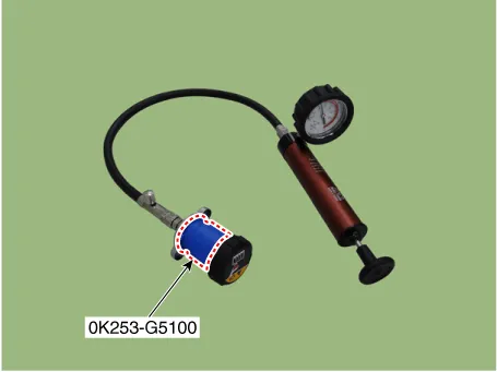
| 2. |
Apply a pressure of 125.52 - 154.94 kpa (1.28 - 1.58 kg/cm², 18.21 - 22.47 psi). |
| 3. |
Check for a drop in pressure. |
| 4. |
If the pressure drops, replace the cap. |
Radiator Leakage Test
| 1. |
Wait until engine is cool, then carefully remove the reservoir tank cap and fill the radiator with engine coolant, then install it on the pressure tester.
|
| 2. |
Apply a pressure tester to the radiator and apply a pressure of 125.52 - 154.94 kpa (1.28 - 1.58 kg/cm², 18.21 - 22.47 psi). |
| 3. |
Inspect for engine coolant leaks and a drop in pressure. |
| 4. |
Remove the tester and reinstall the reservoir tank cap.
|

Components and components location Components 1. Cooling fan 2. Cooling fan motor 3. Cooling fan shroud Specifications Specifications Item Specification Fan type PULLER Fan speed control Resisor Air flow rate (㎥/h) 1,950 - 8% min.
Components and components location Components 1. Water temperature control assembly 2. Engine coolant temperature sensor 3.
Other information:
Kia Optima DL3 2019-2026 Service and Repair Manual: Rear Combination Lamp
Components and components location Component Location 1. Tail lamp 2. Stop lamp 3. Tail/Stop lamp 4. Back up lamp 5. Turn signal lamp Schematic diagrams Connector and Terminal Function [A Type] Pin Function Center Ou
Kia Optima DL3 2019-2026 Service and Repair Manual: Heater Control Unit
Components and components location Components Connector Pin Function [Connector A] Pin NO Funtion Pin NO Funtion 1 Ground 11 Ground 2 Clean signal 12 -
Categories
- Manuals Home
- Kia Optima Owners Manual
- Kia Optima Service Manual
- Body (Interior and Exterior)
- Timing Chain
- Battery
- New on site
- Most important about car
