Kia Optima DL3: Crash Pad / Cowl Cross Bar Assembly
Components and components location
| Component Location |
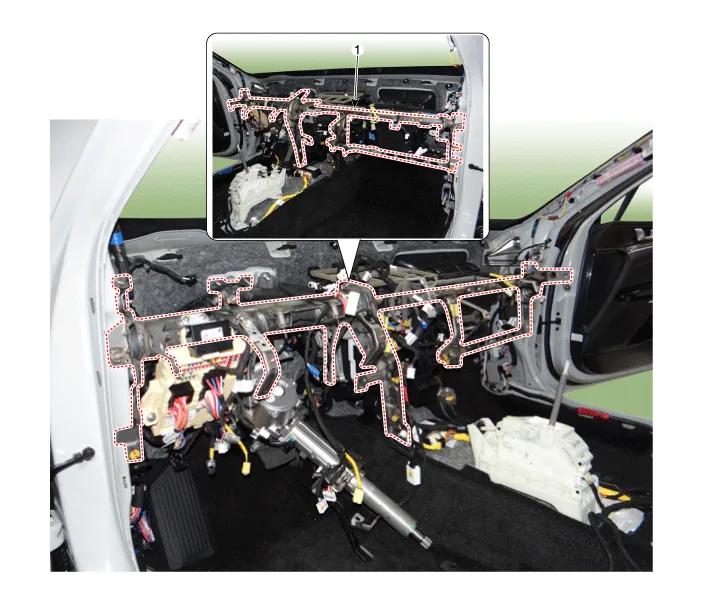
| 1. Cowl cross bar assembly
|
Repair procedures
| Replacement |
|

| 1. |
Disconnect the negative (-) battery terminal. |
| 2. |
Remove the main crash pad assembly. (Refer to Crash Pad - "Main Crash Pad Assembly") |
| 3. |
Remove the knee airbag(KAB). (Refer to Restraint - "Knee Airbag(KAB)") |
| 4. |
Disconnect the steering column connectors. (Refer to Steering System - "Steering Column and Shaft") |
| 5. |
Loosen the mounting nuts and through bolts in the frontal area and lower the steering column. (Refer to Steering System - "Steering Column and Shaft") |
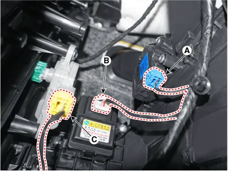
| 6. |
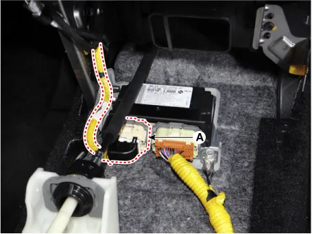
Press the lock pin and separate the airbag system control module connector (A).
|
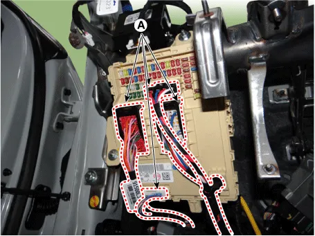
| 7. |
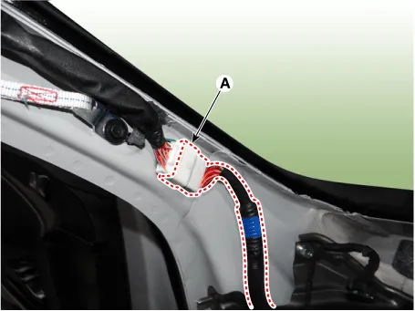
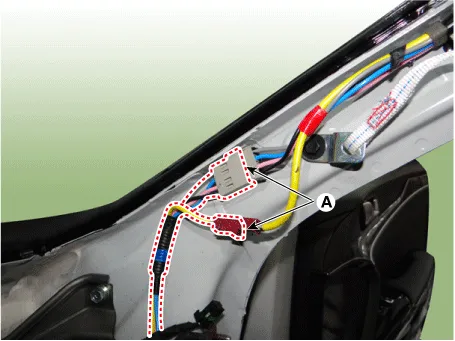
Remove the mounting clips from the front pillar area and disconnect the various connectors (A). [Driver]
[Passenger]
|
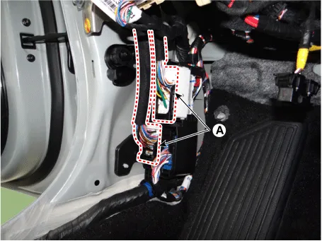
| 8. |
Disconnect the passenger compartment junction box connectors (A).
|
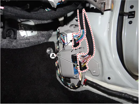
| 9. |
Disconnect the multi box connectors (A). [Driver]
[Passenger]
|
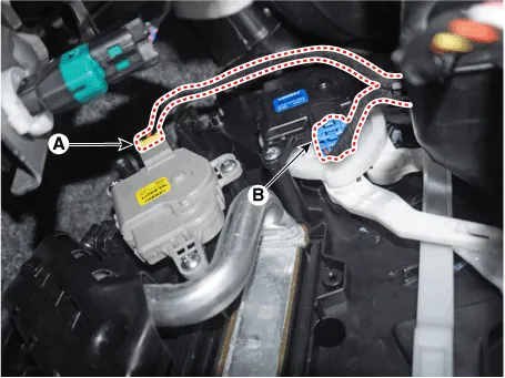
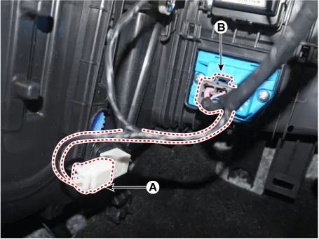
| 10. |
Separate the heater and blower unit connector. [Driver]
[Passenger]
|
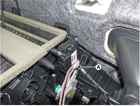
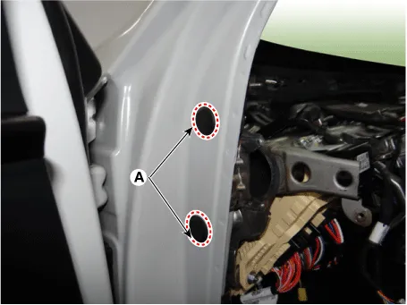
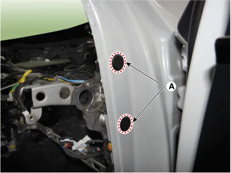
| 11. |
Remove the plug hole (A) and loosen the cowl cross bar side mounting bolts. [LH]
[RH]
|
| 12. |
Remove the battery. G 2.0 NU MPI (Refer to Engine Electrical System - "Battery") G 2.5 GDI THETA II (Refer to Engine Electrical System - "Battery") |
| 13. |
Loosen the engine room cowl cross bar assembly mounting bolts.
|

| 14. |
Loosen the mounting bolts remove the cowl cross bar assembly (A).
|

| 15. |
Separate the main wiring (A) from cowl cross bar assembly.
|


| 16. |
To install, reverse the removal procedure.
|

Components and components location Component Location 1. Main crash pad assembly Repair procedures Replacement • When removing with a flat-tip screwdriver or remover, wrap protective tape around the tools to prevent damage to components.
Components and components location Components [General Type] 1. Sunvisor [LH] 2. Sunvisor [RH] 3. Roof trim [Panorama Sunroof Type] 1.
Other information:
Kia Optima DL3 2019-2026 Service and Repair Manual: Personal Lamp
Repair procedures Removal When removing with a flat-tip screwdriver or remover, wrap protective tape around the tools to prevent damage to components. 1.
Kia Optima DL3 2019-2026 Service and Repair Manual: Compressor oil
Repair procedures Oil Specification 1. The HFC-134a system requires synthetic (PAG) compressor oil whereas the R-12 system requires mineral compressor oil. The two oils must never be mixed. 2. Compressor (PAG) oil varies according to compressor model.
Categories
- Manuals Home
- Kia Optima Owners Manual
- Kia Optima Service Manual
- Lift And Support Points
- Front Axle Assembly
- Identification Numbers
- New on site
- Most important about car
