Kia Optima DL3: Driveshaft and axle / Front Axle Assembly
Components and components location
| Components |
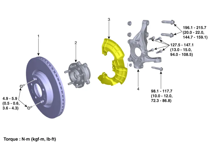
| 1. Front brake disc 2. Front hub assembly |
3. Dust cover 4. Front knuckle |
Repair procedures
| Removal |
| 1. |
Disconnect the (-) battery terminal. |
| 2. |
Remove the front wheel and tire. (Refer to Suspension System - "Wheel") |
| 3. |
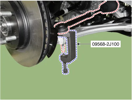
Disconnect the tie rod end ball joint from the knuckle by using the SST (09568-2J100).
|
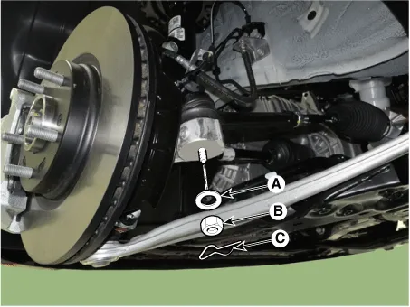

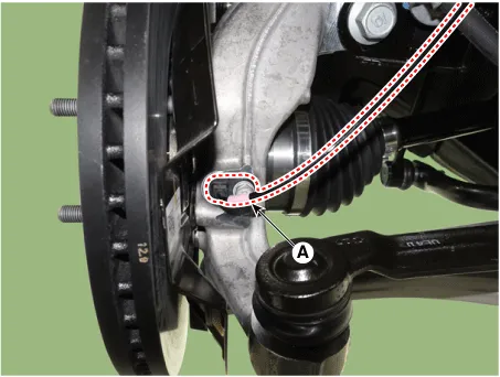
| 4. |
Loosen the lower arm mounting nut (A).
|

| 5. |
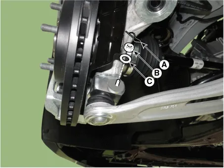
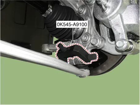
Disconnect lower arm ball joint from the knuckle by using the SST (0K545-A9100).
|
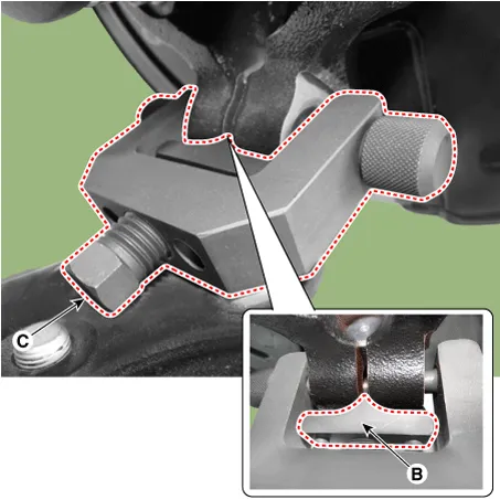

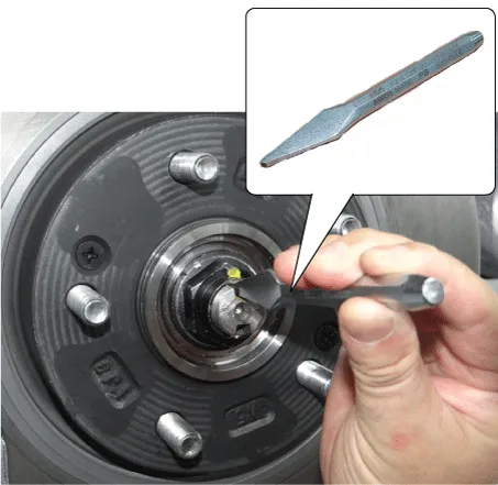
| 6. |
By hammering on a chisel, unlock the driveshaft lock hub nut caulking.
|

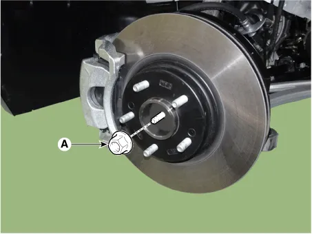
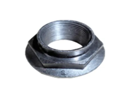
| 7. |
Remove the caulking nut (A) from the front axle.
|

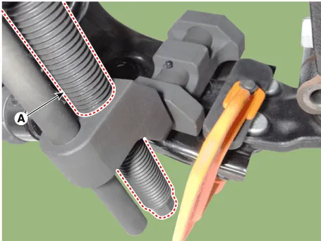
| 8. |
Disconnect the driveshaft from the axle hub by using the SST (09517-4E000).
|

| 9. |
Remove the front brake caliper assembly. (Refer to Brake System - "Front Brake Caliper") |
| 10. |
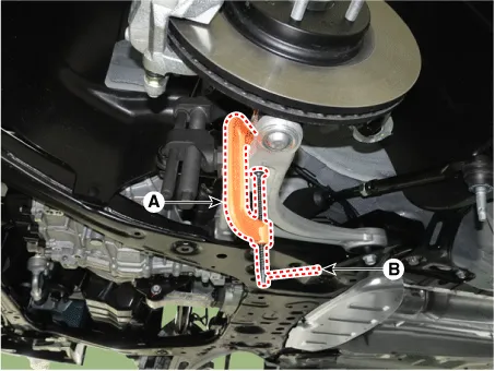
Separate the front wheel speed sensor (A) after loosening the bolt.
|
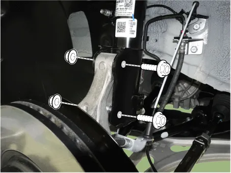
| 11. |
Remove the front axle (A) after loosening the front strut bolts and nuts.
|
| Installation |
| 1. |
Install in the reverse order of removal. |
| 2. |
Check the front alignment. (Refer to Suspension System - "Alignment") |
| Disassembly |
| 1. |
Remove the front brake disc (A) after loosening the screws.
|

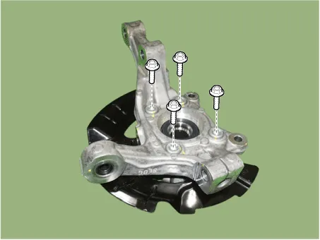
| 2. |
Loosen the hub bearing mounting bolts.
|
| 3. |
Remove the dust cover (A) from the knuckle.
|

| Reassembly |
| 1. |
Assemble in the reverse order of disassembly. |
| Inspection |
| 1. |
Check the hub for cracks and the splines for wear. |
| 2. |
Check the brake disc for scoring and damage. |
| 3. |
Check the knuckle for cracks. |
| 4. |
Check the bearing for cracks or damage. |
Tightening torque Tightening Torque Item N·m kgf·m lb·ft Front Tire wheel hub nut 107.
Components and components location Components 1. Rear brake disc 2. Hub bearing assembly 3. Dust cover 4. Rear carrier Repair procedures Removal 1.
Other information:
Kia Optima DL3 2019-2026 Service and Repair Manual: Power Door Mirror Switch
Schematic diagrams Connector and Terminal Function Pin Function 1 B-CAN (Low) 2 B-CAN (High) 3 Ground (Assist safety) 4 Assist safety 5 LIN (For IMS)
Kia Optima DL3 2019-2026 Service and Repair Manual: Mode Control Actuator
Components and components location Components Location 1. Mode control actuator Description and operation Description The mode control actuator is located at the heater unit. It adjusts the position of the mode door by operating the mode control actuator based on the signal of the A/C co
Categories
- Manuals Home
- Kia Optima Owners Manual
- Kia Optima Service Manual
- Floor Console Assembly
- Body (Interior and Exterior)
- Identification Numbers
- New on site
- Most important about car
