Kia Optima DL3: Engine And Transaxle Assembly / Engine And Transaxle Assembly
Repair procedures
| Removal |
|

|

| 1. |
Remove the engine cover. (Refer to Engine and Transaxle Assembly - "Engine Cover") |
| 2. |
Disconnect the battery negative terminal. |
| 3. |
Remove the battery and battery tray. (Refer to Engine Electrical System - "Battery") |
| 4. |
Remove the air cleaner assembly. (Refer to Intake and Exhaust System - "Air Cleaner") |
| 5. |
Remove the engine room under cover. (Refer to Engine and Transaxle Assembly - "Engine Room Under Cover") |
| 6. |
Drain the engine coolant. (Refer to Cooling System - "Coolant") |
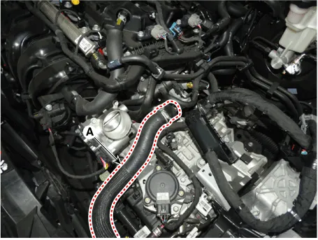
| 7. |
Disconnect the radiator upper hose (A).
|
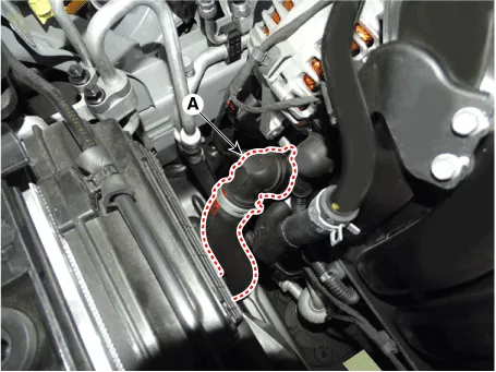
| 8. |
Disconnect the radiator lower hose (A).
|
| 9. |
Recover the refrigerant and then remove the high pressure pipe and low pressure pipe. (Refer to Heating, Ventilation Air conditioning - "Compressor") |
| 10. |
Disconnect the wire harness connectors, control cables and ATF cooler hoses (A/T only) from the transaxle. (Refer to Automatic Transaxle System - "Automatic transaxle") |
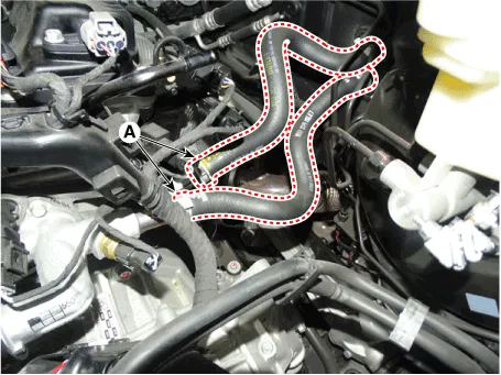
| 11. |
Disconnect the heater hose (A).
|
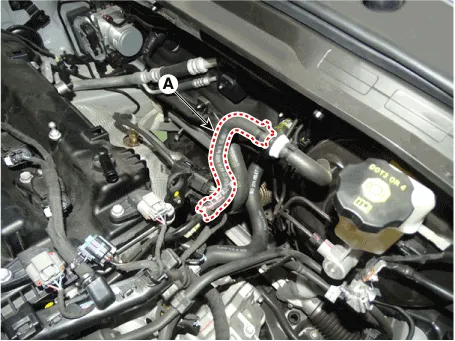
| 12. |
Disconnect the brake booster vacuum hose (A).
|
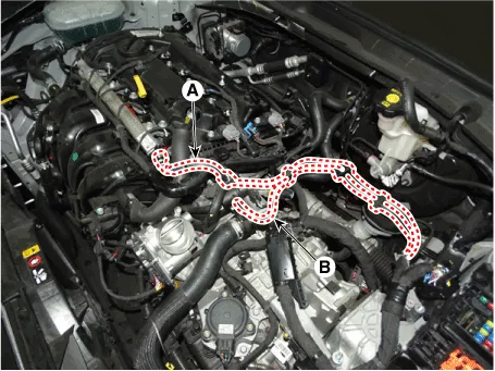
| 13. |
Disconnect the fuel hose (A) and the purge control solenoid valve (PCSV) hose (B).
|
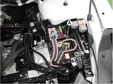
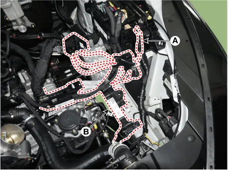
| 14. |
Remove the wiring harness from the engine room.
|
| 15. |
Remove the front muffler. (Refer to Intake and Exhaust System - "Muffler") |
| 16. |
Remove the roll rod bracket (A).
|
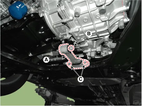
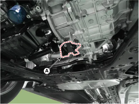
| 17. |
Remove the roll rod mounting support bracket (A).
|
| 18. |
Remove the sub frame. (Refer to Suspension system - "Sub Frame") |
| 19. |
Support the engine and transaxle assembly with a lift table. |
| 20. |
Disconnect the engine ground cable.
|
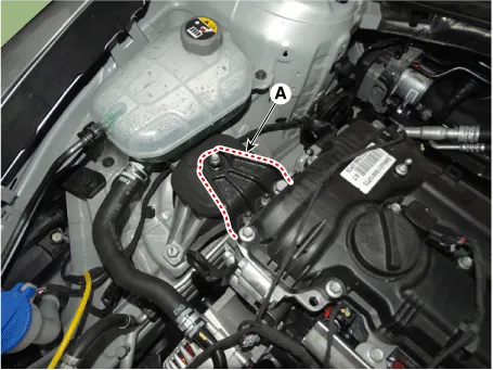
| 21. |
Remove the engine mounting support bracket (A).
|
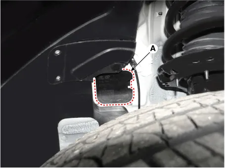
| 22. |
Disconnect the transaxle ground line (A).
|
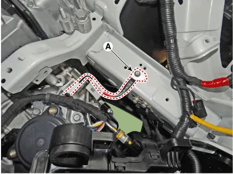
| 23. |
Remove the mounting side pannel packing (A).
|
| 24. |
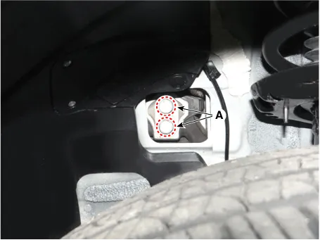
Remove the transaxle mounting bolts (A).
|
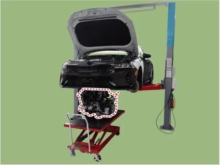
| 25. |
Remove the engine and transaxle assembly (A) by lifting vehicle.
|
| Installation |
Installation is in the reverse order of removal.
Perform the following :
| • |
Refill engine with engine oil. |
| • |
Refill transaxle with fluid. |
| • |
Refill radiator and reservoir tank with engine coolant. |
| • |
Place heater control knob on "HOT" position. |
| • |
Bleed air from the cooling system. |
| – |
Start engine and let it run until it warms up. (until the radiator fan operates 3 or 4 times.) |
| – |
Turn Off the engine. Check the level in the radiator, add coolant if needed. This will allow trapped air to be removed from the cooling system. |
| – |
Put radiator cap on tightly, then run the engine again and check for leaks. |
| • |
Clean battery posts and cable terminals with sandpaper assemble them, then apply grease to prevent corrosion. |
| • |
Inspect for fuel leakage. |
| – |
After assemble the fuel line, turn on the ignition switch (do not operate the starter) so that the fuel pump runs for approximately two seconds and fuel line pressurizes. |
| – |
Repeat this operation two or three times, then check for fuel leakage at any point in the fuel line. |
Components and components location Components 1. Transaxle mounting bracket 2. Roll rod bracket 3. Engine mounting bracket 4.
Other information:
Kia Optima DL3 2019-2026 Service and Repair Manual: Washer Switch
R
Kia Optima DL3 2019-2026 Service and Repair Manual: Auto Defogging Sensor
Description and operation Description The auto defogging sensor is installed on the front window glass. The sensor judges and sends signal if moisture occurs to blow out wind for defogging. The air conditioner control module receives signal from the sensor and restrains moisture and eliminate defog by controlling the intake actu
Categories
- Manuals Home
- Kia Optima Owners Manual
- Kia Optima Service Manual
- Charging System
- Timing Chain
- Cooling System
- New on site
- Most important about car
