Kia Optima DL3: Engine And Transaxle Assembly / Engine Mounting
Components and components location
| Components |
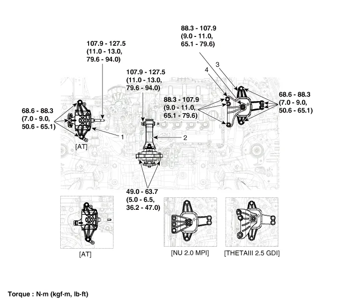
| 1. Transaxle mounting bracket
2. Roll rod bracket |
3. Engine mounting bracket
4. Engine mounting support bracket |
Repair procedures
| Removal and Installation |
Engine Mounting Bracket
| 1. |
Remove the engine room under cover. (Refer to Engine and Transaxle Assembly - "Engine Room Under Cover") |
| 2. |
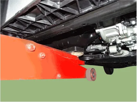
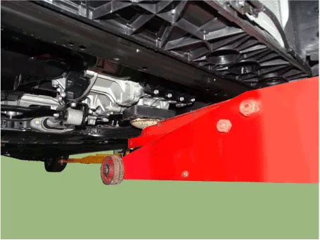
Install the jack under the edge of lower oil pan to support the engine.
|

| 3. |
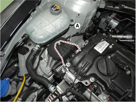
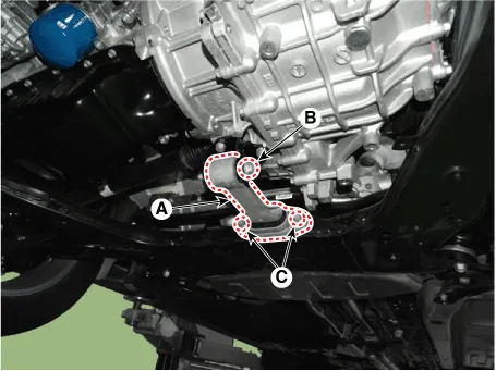
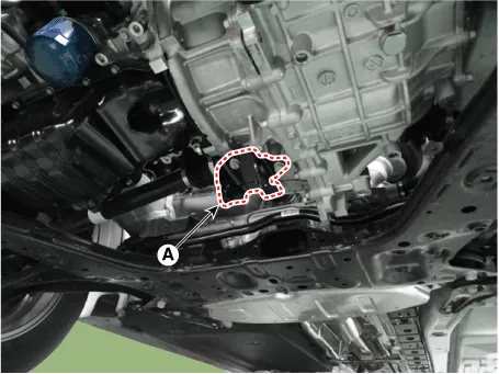
Remove the engine mounting support bracket (A).
|
| 4. |
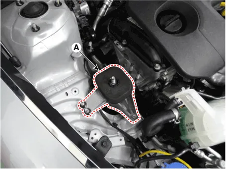
Remove the engine mounting bracket (A).
|
| 5. |
Install in the reverse order of removal. |
Transaxle mounting bracket
| 1. |
Disconnect the battery negative terminal. |
| 2. |
Remove the engine room under cover. (Refer to Engine and Transaxle Assembly - "Engine Room Under Cover") |
| 3. |
Remove the air cleaner assembly. (Refer to Intake and Exhaust System - "Air Cleaner") |
| 4. |
Remove the engine control module (ECM). (Refer to Engine / Fuel System - "Engine Control Module (ECM)") |
| 5. |
Remove the battery and battery tray. (Refer to Engine Electrical System - "Battery") |
| 6. |
Install jack under the transaxle to support it.
|
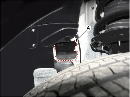
| 7. |
Remove the transaxle mounting side pannel packing (A).
|
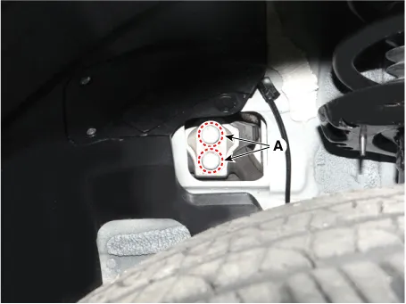
| 8. |
Remove the transaxle support bracket mounting bolt (A).
|
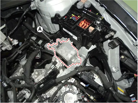
| 9. |
Remove the transaxle mounting bracket (A).
|
| 10. |
Install in the reverse order of removal. |
Roll Rod Bracket
| 1. |
Remove the engine room under cover. (Refer to Engine and Transaxle Assembly - "Engine Room Under Cover") |
| 2. |
Remove the roll rod bracket (A).
|
| 3. |
Remove the roll rod suport bracket (A).
|
| 4. |
Install in the reverse order of removal. |
Repair procedures Removal and Installation Engine Room Under Cover 1. Remove the engine room under cover (A). Tightening torque: 7.
Repair procedures Removal • Use fender covers to avoid damaging painted surfaces.
Other information:
Kia Optima DL3 2019-2026 Service and Repair Manual: Smart Key Diagnostic
Repair procedures Inspection 1. In the body electrical system, failure can be quickly diagnosed by using the vehicle diagnostic system (KDS). The diagnostic system (KDS) provides the following information. (1) Self diagnosis : Checking failure and code number (DTC).
Kia Optima DL3 2019-2026 Service and Repair Manual: Heating, Ventilation and Air Conditioning
Service data Service Data Air Conditioner ltem Specification Compressor Type 6SAS14 Oil type & Capacity ND-OIL 12 80 ± 10 cc (2.82 ± 0.
Categories
- Manuals Home
- Kia Optima Owners Manual
- Kia Optima Service Manual
- Suspension System
- Brake System
- Automatic Transaxle System
- New on site
- Most important about car
