Kia Optima DL3: Engine And Transaxle Assembly / Engine Cover
Repair procedures
| Removal and Installation |
| 1. |
Remove the engine cover (A).
|
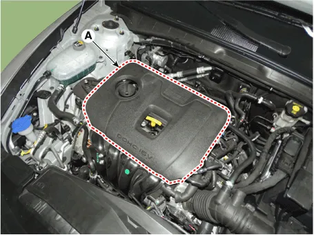

| 2. |
Install in the reverse order of removal. |
Repair procedures Removal and Installation Engine Room Under Cover 1. Remove the engine room under cover (A). Tightening torque: 7.
Other information:
Kia Optima DL3 2019-2026 Service and Repair Manual: Power Door Lock Switch
Repair procedures Inspection Power Window Main Switch Diagnosis With KDS 1. In the body electrical system, failure can be quickly diagnosed by using the vehicle diagnostic system (KDS). The diagnostic system (KDS) provides the following information.
Kia Optima DL3 2019-2026 Service and Repair Manual: Power Door Lock Module
Repair procedures Inspection When prying with a flat-tip screwdriver or use a prying trim tool, wrap it with protective tape, and apply protective tape around the related parts, to prevent damage.
Categories
- Manuals Home
- Kia Optima Owners Manual
- Kia Optima Service Manual
- Steering System
- Brake System
- Motor Driven Power Steering
- New on site
- Most important about car
