Kia Optima DL3: Engine And Transaxle Assembly / Engine Room Under Cover
Repair procedures
| Removal and Installation |
Engine Room Under Cover
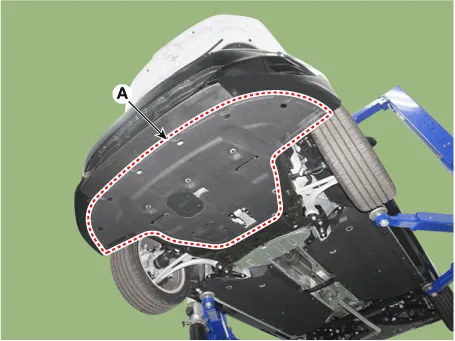
| 1. |
Remove the engine room under cover (A).
|
| 2. |
Install in the reverse order of removal. |
Repair procedures Removal and Installation 1. Remove the engine cover (A). • To avoid damage, remove the engine cover on room temperature.
Components and components location Components 1. Transaxle mounting bracket 2. Roll rod bracket 3. Engine mounting bracket 4.
Other information:
Kia Optima DL3 2019-2026 Service and Repair Manual: Rear Glass Defogger Printed Heater
Repair procedures Inspection • Wrap tin foil around the end of the voltmeter test lead to prevent damaging the heater line. Apply pressure on the tin foil with hand and move the tin foil along the grid line to check for open circ
Kia Optima DL3 2019-2026 Service and Repair Manual: Heater & A/C Control Unit (Manual)
Components and components location Components Connector Pin Function [Connector A] Pin NO Funtion Pin NO Funtion 1 Battery (+) 21 IGN2 2 ILL+ (TAIL) 22 IGN1
Categories
- Manuals Home
- Kia Optima Owners Manual
- Kia Optima Service Manual
- Lift And Support Points
- Brake System
- Cooling System
- New on site
- Most important about car
