Kia Optima DL3: Button Engine Start System / ESCL(Electronic Steering Column Lock)
Schematic diagrams
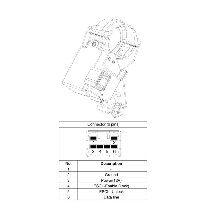
| Connector and Terminal funciton |
Repair procedures
| Removal |
| 1. |
Disconnect the negative battery terminal. |
| 2. |
Remove the crash pad lower panel. (Refer to Body - "Crash Pad Lower Panel") |
| 3. |
Remove the steering column upper and lower shrouds. (Refer to Body - "Steering Column Shroud Panel") |
| 4. |
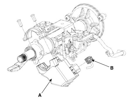
Remove the electronic steering column lock (A) by loosening the mounting bolts after disconnecting the connector (B).
|
| Installation |
| 1. |
Install in the reverse order of removal.
|

Schematic diagrams Connector and Terminal function Repair procedures Removal 1. Disconnect the negative battery terminal.
Other information:
Kia Optima DL3 2019-2026 Service and Repair Manual: Air Conditioning System
General safety information and caution Instructions (R-134a) When Handling Refrigerant 1. R-134a liquid refrigerant is highly volatile. A drop on the skin of your hand could result in localized frostbite. When handling the refrigerant, be sure to wear gloves.
Kia Optima DL3 2019-2026 Service and Repair Manual: Ambient Temperature Sensor
Description and operation Description The ambient temperature sensor is located at the front of the condenser and detects ambient air temperature. It is a negative type thermistor; resistance will increase with lower temperature, and decrease with higher temperature.
Categories
- Manuals Home
- Kia Optima Owners Manual
- Kia Optima Service Manual
- Lift And Support Points
- Body (Interior and Exterior)
- Automatic Transaxle System
- New on site
- Most important about car
