Kia Optima DL3: Air Conditioning System / Ambient Temperature Sensor
Description and operation
| Description |
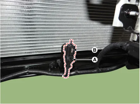
The ambient temperature sensor is located at the front of the condenser and detects ambient air temperature. It is a negative type thermistor; resistance will increase with lower temperature, and decrease with higher temperature.
The sensor output will be used for discharge temperature control, temperature regulation door control, blower motor level control, mix mode control and in-car humidity control.

|

Repair procedures
| Inspection |
| 1. |
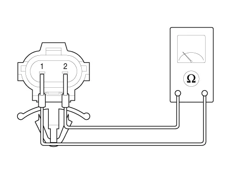
Check the resistance of the ambient temperature sensor between terminals 1 and 2 whether it changes by changing the ambient temperature.
Specification
|
| Replacement |
| 1. |
Disconnect the negative (-) battery terminal. |
| 2. |
Remove the front bumper assembly. (Refer to Body - "Front Bumper Assembly") |
| 3. |
Separate the connector (A) and remove the ambient temperature sensor (B).
|
| 4. |
To install, reverse the removal procedure.
|

Description and operation Description The photo sensor is located at the center of the defrost nozzles. The photo sensor contains a photovoltaic (sensitive to sunlight) diode.
Description and operation Description The auto defogging sensor is installed on the front window glass. The sensor judges and sends signal if moisture occurs to blow out wind for defogging.
Other information:
Kia Optima DL3 2019-2026 Service and Repair Manual: Personal Lamp
Repair procedures Removal When removing with a flat-tip screwdriver or remover, wrap protective tape around the tools to prevent damage to components. 1.
Kia Optima DL3 2019-2026 Service and Repair Manual: Intake Actuator
Components and components location Components Location 1. Intake actuator Description and operation Description The intake actuator is located at the blower unit. It regulates the intake door by a signal from the control unit.
Categories
- Manuals Home
- Kia Optima Owners Manual
- Kia Optima Service Manual
- Front Axle Assembly
- Motor Driven Power Steering
- Steering System
- New on site
- Most important about car
