Kia Optima DL3: Button Engine Start System / Start/Stop Button
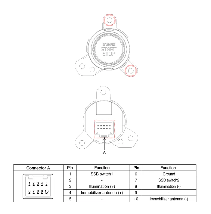
Schematic diagrams
| Connector and Terminal function |
Repair procedures
| Removal |
| 1. |
Disconnect the negative battery terminal. |
| 2. |
Remove the crash pad garnish [RH]. (Refer to Body - "Crash Pad Garnish") |
| 3. |
Remove the center air vent garnish (A) by loosening the mounting screws.
|

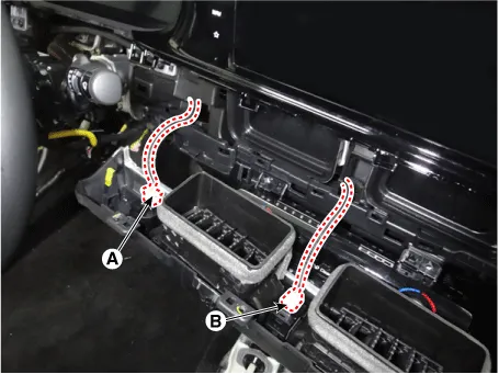
| 4. |
Disconnect the start/stop button connector (A) and hazard lamp switch connector (B).
|
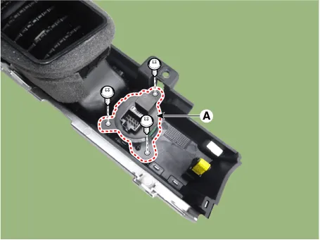
| 5. |
Remove the start/stop button (A) by loosening the mounting screws.
|
| Installation |
| 1. |
Install in the reverse order of removal. |
Components and components location Components (1) 1. Integrated body control unit (IBU) 2. Interior antenna 1 3.
Schematic diagrams Connector and Terminal funciton Repair procedures Removal 1. Disconnect the negative battery terminal.
Other information:
Kia Optima DL3 2019-2026 Service and Repair Manual: Trunk Room Lamp
Repair procedures Removal 1. Disconnect the negative battery terminal. 2. Remove the trunk room lamp (A) by pressing the hook. 3. Disconnect the trunk room lamp connector (A).
Kia Optima DL3 2019-2026 Service and Repair Manual: Cluster Ionizer
Components and components location Components Location 1. Condenser Description and operation Description The cluster ionizer makes disinfection and decomposition of bad smell from the air-conditioner or inflow air.
Categories
- Manuals Home
- Kia Optima Owners Manual
- Kia Optima Service Manual
- Lift And Support Points
- Floor Console Assembly
- Timing Chain
- New on site
- Most important about car
