Kia Optima DL3: Hydraulic System / Oil Pump
Repair procedures
| Removal |
If ATF is leaking due to damage on O-ring, replace O-ring with a new one. (Refer to Oil Pump - "Replacement")
|

| Oil Pump Assembly |
| 1. |
Remove the automatic transaxle assembly. (Refer to Automatic Transaxle System - "Automatic Transaxle") |
| 2. |
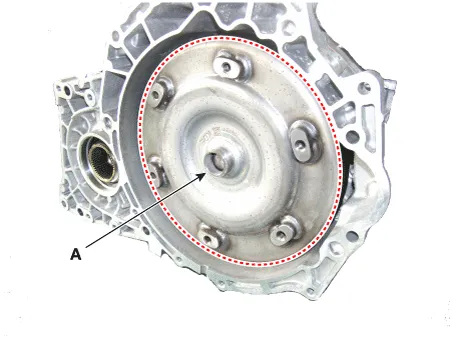
Remove the torque converter (A).
|
| 3. |
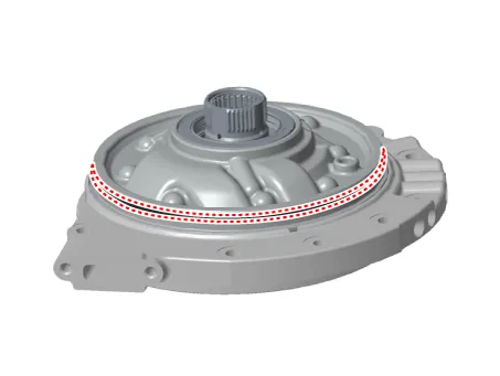
Remove the converter housing (A) from the transaxle case (B).
|
| 4. |
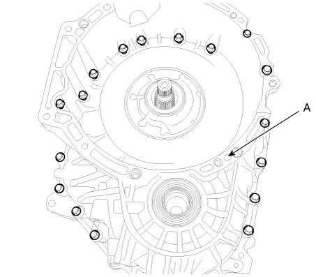
Remove the oil filter (B) after loosening the bolts (A).
|
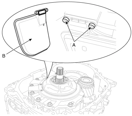
| 5. |
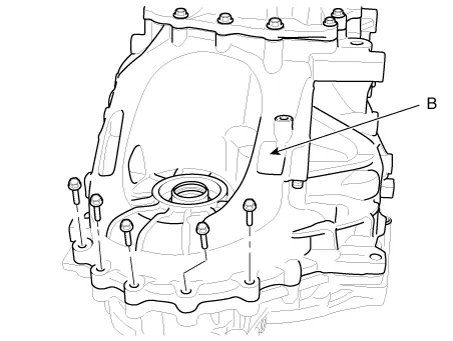
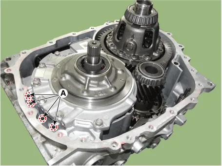
Remove the oil pump (A) by loosening the bolts.
|
| 6. |
Remove the thrust washer (A) from the oil pump (B).
|
| Installation |
| 1. |
Assemble the thrust washer (A) to the oil pump assembly (B).
|
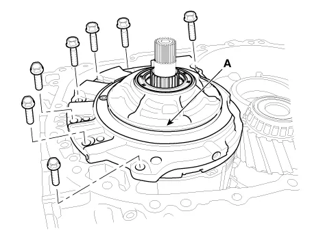
| 2. |
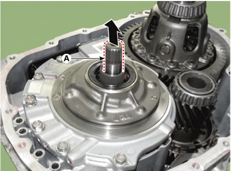
Install the oil pump assembly (A).
|
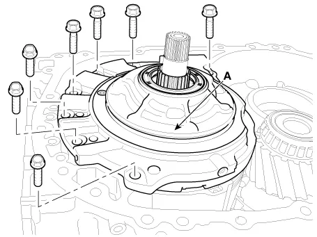
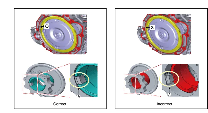
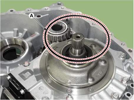
| 3. |
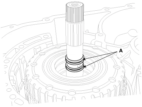
After tighten the oil pump mounting bolts, check if the movement of input shaft is 0.55 - 0.85 mm (0.0217 - 0.03346457 in.) by pulling the spline (A) to upward direction.
|
| 4. |
Install the oil filter (A).
|
| 5. |
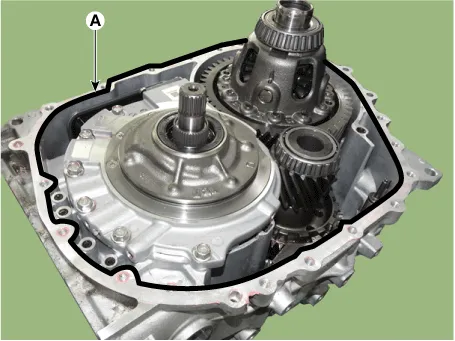
Apply the sealant (A) on the transaxle case surface.
|
| 6. |
Install the converter housing (A) on the transaxle case (B).
|
| 7. |
Install the torque converter (A).
|
| 8. |
Install the automatic transaxle assembly. (Refer to Automatic Transaxle System - "Automatic Transaxle") |
| Replacement |
| O-Ring |
| 1. |
Remove the automatic transaxle assembly. (Refer to Automatic Transaxle System - "Automatic Transaxle") |
| 2. |
Remove the torque converter.
|
| 3. |
Remove the clutch housing (A) from the transaxle case (B).
|
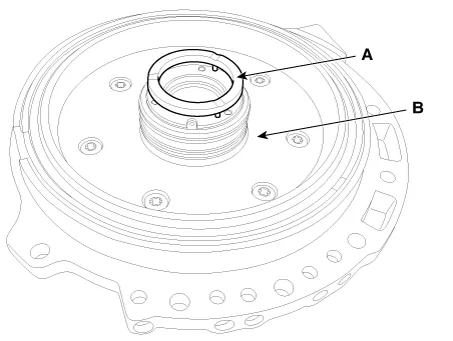
| 4. |
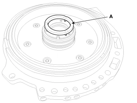
Replace the O-ring (A) with a new one.
|
| 5. |
Apply the sealant (A) on the transaxle case surface.
|
| 6. |
Install the converter housing (A) on the transaxle case (B).
|
| 7. |
Install the torque converter (A).
|
| 8. |
Install the automatic transaxle assembly. (Refer to Automatic Transaxle System - "Automatic Transaxle") |
Repair procedures Replacement It is not recommended to replace the valve body .
Specifications Specification Control type N/L (Normal Low) Control pressure kpa (kgf/cm², psi) 0 - 519.
Other information:
Kia Optima DL3 2019-2026 Service and Repair Manual: Power Door Lock Switch
Repair procedures Inspection Power Window Main Switch Diagnosis With KDS 1. In the body electrical system, failure can be quickly diagnosed by using the vehicle diagnostic system (KDS). The diagnostic system (KDS) provides the following information.
Kia Optima DL3 2019-2026 Service and Repair Manual: Power Door Lock Module
Repair procedures Inspection When prying with a flat-tip screwdriver or use a prying trim tool, wrap it with protective tape, and apply protective tape around the related parts, to prevent damage.
Categories
- Manuals Home
- Kia Optima Owners Manual
- Kia Optima Service Manual
- Headlamps
- Identification Numbers
- Automatic Transaxle System
- New on site
- Most important about car
