Kia Optima DL3: Panorama Sunroof / Panorama Sunroof Motor
Schematic diagrams
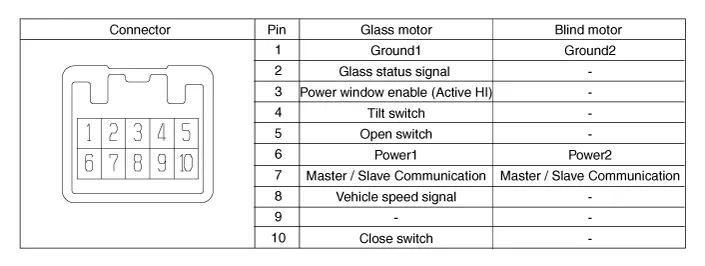
| Connector and Terminal Function |
Repair procedures
| Inspection |
| 1. |
Disconnect the negative battery terminal. |
| 2. |
Remove the rear pillar trim [LH]. (Refer to Body - "Rear Pillar Trim") |
| 3. |
Disconnect the panorama sunroof wiring connector.
|
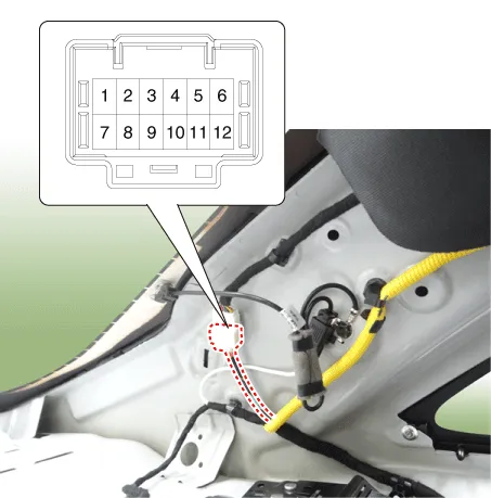
| 4. |
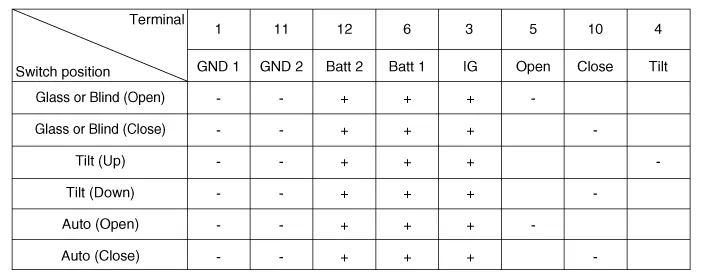
Ground the terminals as below table, and check that the panorama sunroof unit operates.
|
| Removal |
| 1. |
Disconnect the negative battery terminal. |
| 2. |
Remove the roof trim assembly. (Refer to Body - "Roof Trim Assembly") |
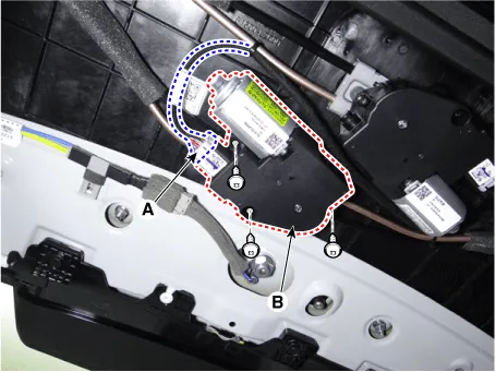
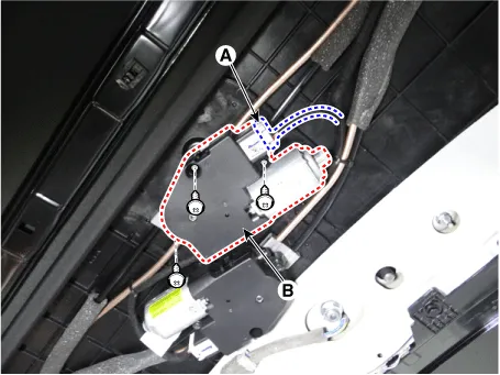
| 3. |
Remove the motor (B) by loosenig the screws after disconnecting the connector (A). [Glass Motor]
[Blind motor]
|
| Installation |
| 1. |
Install in the reverse order of removal. |
| Adjustment |
Panorama Sunroof Reset Procedure
If sunroof glass or roller blind do not operate in automatic mode but operates manually, initialization procedure must be performed as below.
In the following cases, perform initialization as the initial value of sunroof motor has been erased.
|

| 1. |
Ignition “ON”. |
| 2. |
Ensure the roller blind and sunroof glass are fully closed. |
| 3. |
Fully depress and hold the sunroof switch in the closed position and DO NOT release it until the roller blind fully opens and the sunroof glass vent position opens (about 15-20 seconds). |
| 4. |
Once the vent opens, release the switch for 1 second and fully depress and hold the sunroof switch in the closed position again until sunroof glass fully opens then closes and the sunshade fully closes. |
| 5. |
Release the switch and test for proper operation. |
Schematic diagrams Connector and Terminal Function Repair procedures Inspection 1. Remove the overhead console lamp.
Components and components location Component Location 1. Hood switch 2. Integrated Body Control Unit (IBU) 3. Horn 4.
Other information:
Kia Optima DL3 2019-2026 Service and Repair Manual: Washer Motor
Repair procedures Inspection Washer Motor 1. With the washer motor connected to the reservoir tank, fill the reservoir tank with water. Before filling the reservoir tank with water, check the filter for foreign mat
Kia Optima DL3 2019-2026 Service and Repair Manual: Blower Resistor
Repair procedures Inspection 1. Measure the resistance between the terminals. 2. measured resistance is not within specification, the blower resistor must be replaced. (After removing the resistor) (1) Pin No 1.
Categories
- Manuals Home
- Kia Optima Owners Manual
- Kia Optima Service Manual
- Front Axle Assembly
- Automatic Transaxle System
- Motor Driven Power Steering
- New on site
- Most important about car
