Kia Optima DL3: Rear Seat / Rear Seat Assembly
Components and components location
| Component Location |
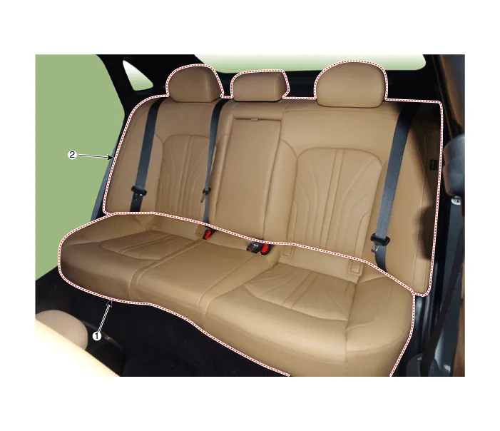
| 1. Rear seat cushion assembly
|
2. Rear seat back assembly
|
Repair procedures
| Replacement |
[Rear seat cushion assembly]
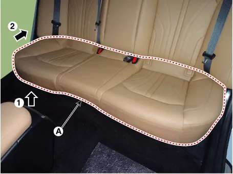
| 1. |
Remove the rear seat cushion assembly (A) by lifting and pulling the front.
|
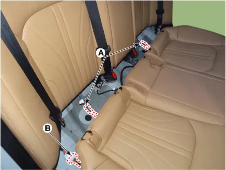
| 2. |
Separate the rear seat cushion heating connector (A) and rear seat extension connector (B).
|
| 3. |
To install, reverse the removal procedure.
|

[Rear seat back assembly]
| 1. |
Remove the rear seat cushion assembly. (Refer to Rear Seat - "Rear Seat Assembly") |
| 2. |
Loosen the mounting bolts and pull the rear seat back assembly (A) upwards to remove.
|
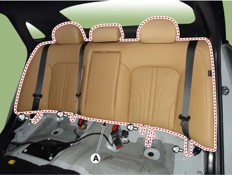
| 3. |
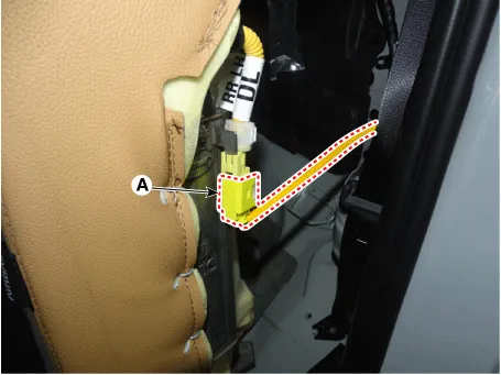
Press the lock pin and separate the rear seat airbag connectors (A).
|
| 4. |
To install, reverse the removal procedure.
|
Components and components location Component Location 1. Rear seat back cover Repair procedures Replacement 1.
Other information:
Kia Optima DL3 2019-2026 Service and Repair Manual: In-car Sensor
Description and operation Description The In-car air temperature sensor is built in the heater & A/C control unit. The sensor contains a thermistor which measures the temperature of the inside. The signal decided by the resistance value which changes in accordance with perceived inside temperature, is delivered to heater co
Kia Optima DL3 2019-2026 Service and Repair Manual: Photo Sensor
Description and operation Description The photo sensor is located at the center of the defrost nozzles. The photo sensor contains a photovoltaic (sensitive to sunlight) diode. The solar radiation received by its light receiving portion, generates an electromotive force in proportion to the amount of radiation received which is
Categories
- Manuals Home
- Kia Optima Owners Manual
- Kia Optima Service Manual
- Lift And Support Points
- Body Electrical System
- Motor Driven Power Steering
- New on site
- Most important about car
