Kia Optima DL3: Steering System / Steering wheel
Components and components location
| Components |
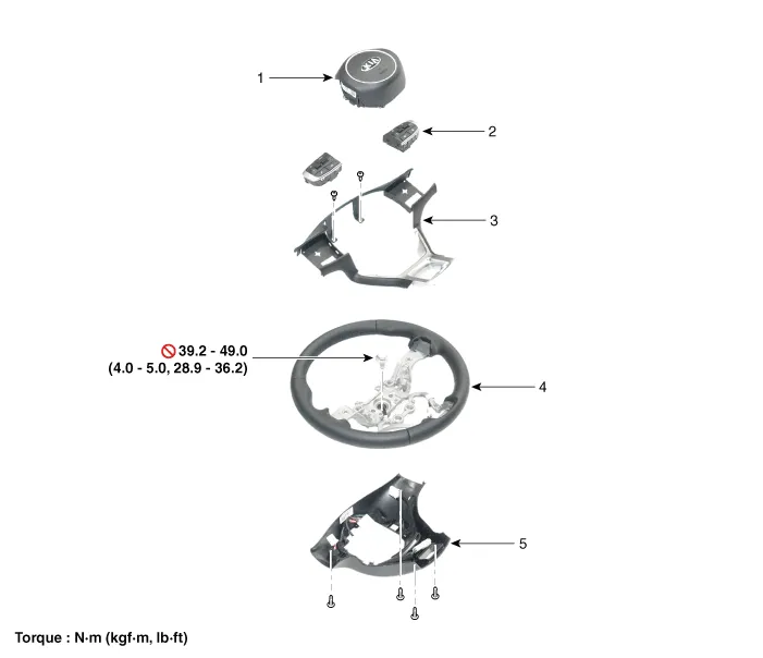
| 1. Drive
air bag module (DAB) 2. Remote control swtich 3. Steering wheel bezel |
4. Steering
wheel 5. Lower cover |
Repair procedures
| Removal |
| 1. |
Align the front wheels facing straight ahead by turning steering wheel.
|

| 2. |
Disconnect the battery (-) terminal. |
| 3. |
Remove the driver airbag module. (Refer to Restraint - "Driver Airbag (DAB) Module and Clock Spring") |
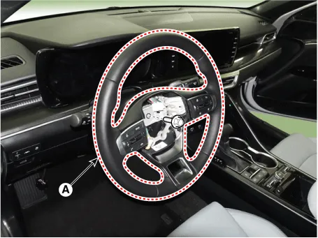
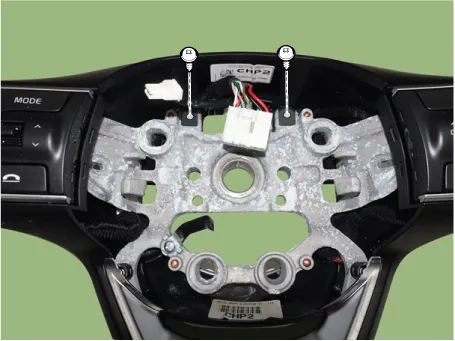
| 4. |
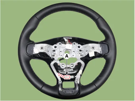
Disconnect the steering wheel connector (A).
|

| 5. |
Remove the steering wheel (A) after loosening the lock bolt.
|
| Disassembly |
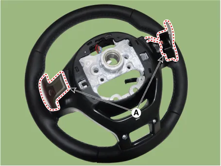
| 1. |
Loosen the paddle shift switch mounting screw.
|
| 2. |
Remove paddle shift connector and remove paddle shift (A).
|
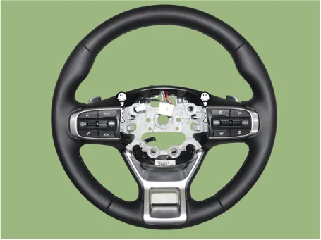
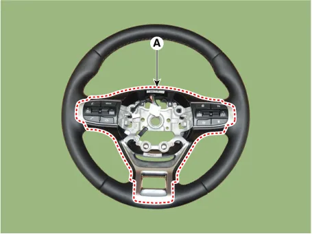
| 3. |
Remove the steering wheel ornament
|
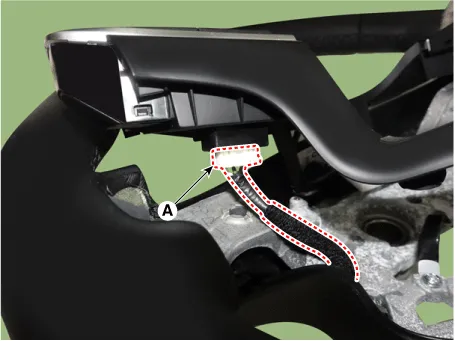
| 4. |
Disconnect the heated steering wheel connector (A) and then remove the steering wheel lower cover.
|
| Assembly |
|
| 1. |
Assemble in the reverse order of disassembly. |
| Installation |
| 1. |
Install in the reverse order of removal. |
Service data Service Data Item Specification Type Electric Power Steering System Steering gear Type Rack & Pinion Rack stroke 156 ± 1 mm (6.
Description and operation Discription The heated steering wheel system improves the themal comfort of the driver by heated the steering wheel when manually selected.
Other information:
Kia Optima DL3 2019-2026 Service and Repair Manual: Integrated Body Control Unit (IBU)
Components and components location Component Location 1. Integrated Body Control Unit (IBU) Schematic diagrams Connector and Terminal Function [Non-Smart key] Pin Function Connector A Connector B
Kia Optima DL3 2019-2026 Service and Repair Manual: Blower Unit
Components and components location Component Location 1. Blower unit assembly Components 1. Intake actuator 2. Cluster ionizer 3. Air filter 4. Blower motor assembly 5.
Categories
- Manuals Home
- Kia Optima Owners Manual
- Kia Optima Service Manual
- Floor Console Assembly
- Battery
- Suspension System
- New on site
- Most important about car
