Kia Optima DL3: Steering wheel / Heated Steering wheel
Description and operation
| Discription |
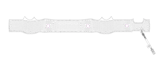
The heated steering wheel system improves the themal comfort of the driver by heated the steering wheel when manually selected.
| 1. |
Heated pad
|
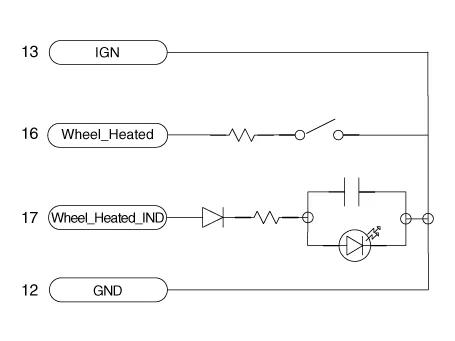
Schematic diagrams
| System Circuit Diagram |
Heated steering wheel pad
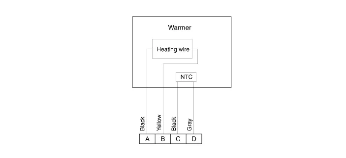
Harness Connector

| Terminal Function |
|
Housing |
Pin |
Function |
Wire color |
|
Pad |
1 |
GROUND |
Black |
|
2 |
HEATER |
Yellow |
|
|
3 |
NTC - |
Black |
|
|
4 |
NTC + |
Gray |
Repair procedures
| Inspection |
| 1. |
Measure a resistance of NTC and Heated pad.
|
| 2. |
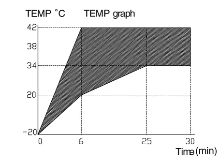
Measure a temperature.
|
| 3. |
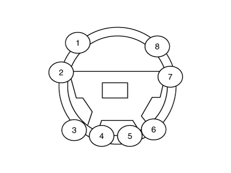
Check for continuity between the terminals in each heated steering switch.
|
Components and components location Components 1. Drive air bag module (DAB) 2. Remote control swtich 3. Steering wheel bezel 4.
Description and operation Description The Motor Driven Power Steering (MDPS) system uses an electric motor to assist the steering force and it is an engine operation independent steering system.
Other information:
Kia Optima DL3 2019-2026 Service and Repair Manual: Lighting System
Specifications Specification Item Tyep Watt (W) Front Headlamp A Type High beam LED - Low beam LED - Position/DRL LED -
Kia Optima DL3 2019-2026 Service and Repair Manual: Heater Core
Repair procedures Replacement 1. Disconnect the negative (-) battery terminal. 2. Remove the heater and blower assembly. (Refer to Heater - "Heater Unit") 3. Loosen the mounting screws and remove the heater core cover (A).
Categories
- Manuals Home
- Kia Optima Owners Manual
- Kia Optima Service Manual
- Steering System
- Headlamps
- Automatic Transaxle System
- New on site
- Most important about car
