Kia Optima DL3: Charging System / USB Charger
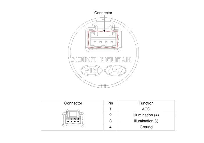
Schematic diagrams
| Connector and Terminal function |
Repair procedures
| Removal |
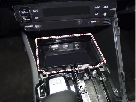
[Floor Console Tray]
| 1. |
Disconnect the negative battery terminal. |
| 2. |
Remove the console upper cover. (Refer to Body - "Floor Console Assembly") |
| 3. |
Remove the floor console tray (A) by using a screwdriver or remover.
|
| 4. |
Disconnect the all connector from the floor console tray.
|
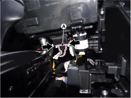
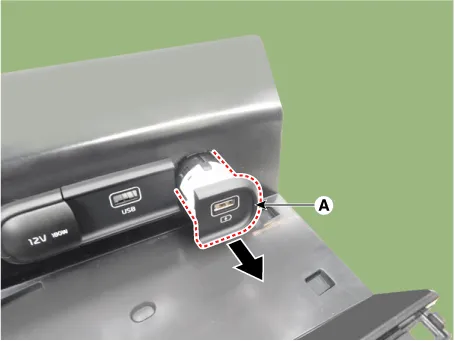
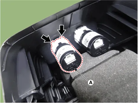
| 5. |
Disconnect the USB charger connector (A).
|
| 6. |
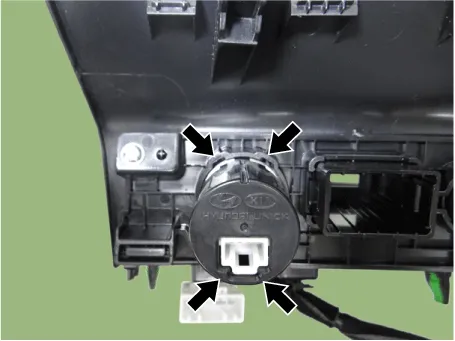
Remove the USB charger (A) by pressing the hooks.
|
[Rear Console Cover]
| 1. |
Disconnect the negative battery terminal. |
| 2. |
Remove the floor console assembly. (Refer to Body - "Floor Console Assembly") |
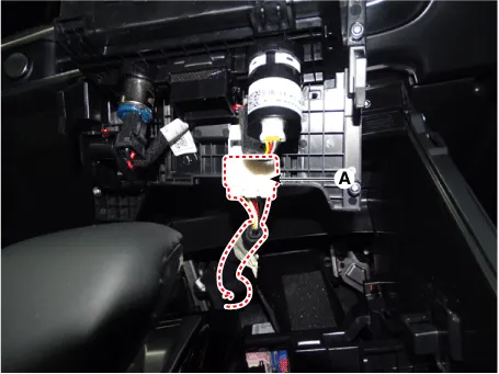
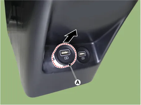
| 3. |
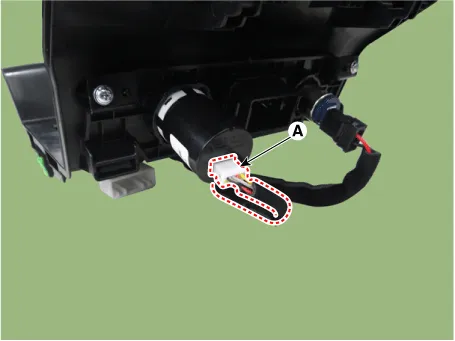
Disconnect the USB charger connector (A).
|
| 4. |
Remove the USB charger (A) by pressing the hooks.
|
[Console Armrest]
| 1. |
Disconnect the negative battery terminal. |
| 2. |
Remove the floor console assembly. (Refer to Body - "Floor Console Assembly") |
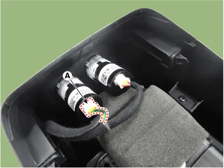
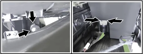
| 3. |
Disconnect the USB charger connector (A).
|

| 4. |
Remove the USB charger (A) by pressing the hooks.
|

| Installation |
| 1. |
Install in the reverse order of removal. |
Specifications Specifications Items Specification Operating voltage DC 9 - 16 V Operating temperature -22 to 167 °F (-30 to +75 °C) Dark current MAX.
Other information:
Kia Optima DL3 2019-2026 Service and Repair Manual: Rear Combination Lamp
Components and components location Component Location 1. Tail lamp 2. Stop lamp 3. Tail/Stop lamp 4. Back up lamp 5. Turn signal lamp Schematic diagrams Connector and Terminal Function [A Type] Pin Function Center Ou
Kia Optima DL3 2019-2026 Service and Repair Manual: Rear Glass Defogger
C
Categories
- Manuals Home
- Kia Optima Owners Manual
- Kia Optima Service Manual
- Motor Driven Power Steering
- Steering System
- Brake System
- New on site
- Most important about car
