Kia Optima DL3: Lighting System / Rear Combination Lamp
Components and components location
| Component Location |

| 1. Tail lamp 2. Stop lamp 3. Tail/Stop lamp |
4. Back up lamp 5. Turn signal lamp |
Schematic diagrams
| Connector and Terminal Function |
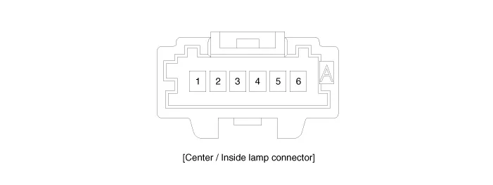
[A Type]
|
Pin |
Function |
|
|
Center |
Outside |
|
|
1 |
Tail lamp (+) Bulb |
Tail lamp (+) Bulb |
|
2 |
- |
Stop lamp (+) Bulb |
|
3 |
Back up lamp (+) Bulb |
Turn signal lamp (+) Bulb |
|
4 |
- |
- |
|
5 |
Ground (-) Bulb |
Ground (-) Bulb |
|
6 |
- |
- |
[B Type]
|
Pin |
Function |
|
|
Center |
Outside |
|
|
1 |
Tail lamp (+) LED |
Tail lamp (+) LED |
|
2 |
Stop lamp (+) LED |
Stop lamp (+) LED |
|
3 |
Back up lamp (+) Bulb |
Turn signal lamp (+) Bulb |
|
4 |
- |
- |
|
5 |
Ground (-) Bulb |
Ground (-) Bulb |
|
6 |
Ground (-) LED |
Ground (-) LED |
Repair procedures
| Removal |
[Outside]
| 1. |
Disconnect the negative battery terminal. |
| 2. |
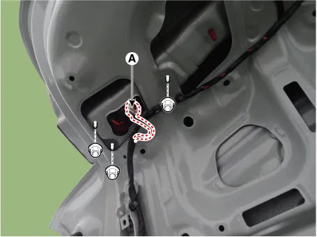
Remove the rear combination lamp service cover (A).
|
| 3. |
Disconnect the rear combination lamp connector (A) after loosening the nuts.
|
| 4. |
Remove the rear combination lamp (A).
|
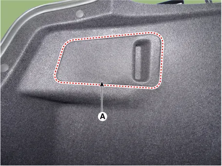
[Center]
| 1. |
Disconnect the negative battery terminal. |
| 2. |
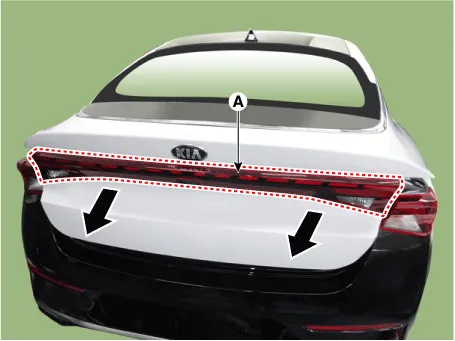
Remove the trunk lid trim. (Refer to Body - "Trunk Lid Trim") |
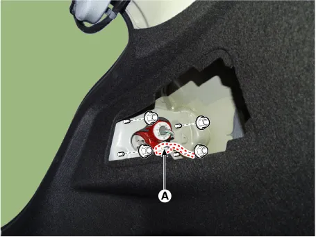
| 3. |
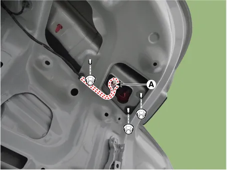
Disconnect the rear combination lamp connector (A) after loosening the nuts. [LH]
[RH]
[Center]
|

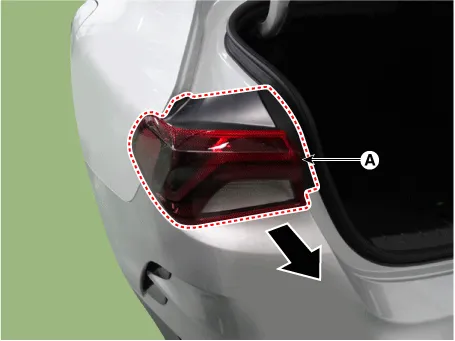
| 4. |
Remove the rear combination lamp (A).
|
| Installation |
| 1. |
Install in the reverse of the removal. |
| Replacement |
| Bulb |
[Turn signal lamp]
| 1. |
Remove the outside rear combination lamp. |
| 2. |
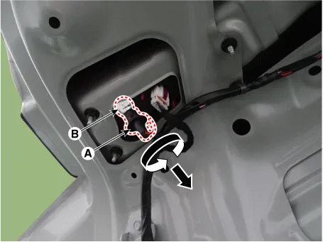
Remove the socket (A) by rotating in the counterclockwise. |
| 3. |
Replace the bulb (B) from the socket.
|

[Backup lamp]
| 1. |
Disconnect the negative battery terminal. |
| 2. |
Remove the trunk lid trim. (Refer to Body - "Trunk Lid Trim") |
| 3. |
Remove the socket (A) by rotating in the counterclockwise. |
| 4. |
Replace the bulb (B) from the socket.
|
Schematic diagrams Connector and Terminal Function [A Type] Connector A Pin E xcept Russia Region Russia only Function Function 1 Battery (+) Battery (+) 2 IGN1 (PAB) - 3 IGN1 (SBR) - 4 eCall PWM - 5 - - 6 eCall botton eCall botton 7 - - 8 eCall ground eCall ground 9 Ground (Room, Door lamp) Ground (Room, Door lamp) 10 PAB ON - 11 PAB OFF - 12 Ground (PAB, SBR) - 13 LED (Red) LED (Red) 14 LED (Green) LED (Green) 15 ACC - 16 Botton back light Botton back light 17 - - 18 Door (-) Door (-) 19 Room lamp signal Room lamp signal 20 SBR (Rear left) - 21 SBR (Rear center) - 22 SBR (Rear Right) - 23 Ground (eCall MCU) - 24 Ground (eCall LED) Ground (eCall LED) [B Type] Connector A Pin Except Russia Region R ussia only Function Function 1 Battery (+) Battery (+) 2 IGN1 (PAB) IGN1 (PAB) 3 - - 4 eCall PWM - 5 - - 6 eCall botton eCall botton 7 - - 8 IGN1 (ETCS) IGN1 (ETCS) 9 Ground (PAB, SBR, TMU) Ground (PAB, SBR, TMU) 10 - - 11 - - 12 eCall ground eCall ground 13 Ground (Room, Door lamp) Ground (Room, Door lamp) 14 PAB ON PAB ON 15 PAB OFF PAB OFF 16 Door (-) Door (-) 17 LED (Red) LED (Red) 18 LED (Green) LED (Green) 19 ACC - 20 Botton back light Botton back light 21 IGN1 (SBR) IGN1 (SBR) 22 Room lamp signal Room lamp signal 23 - - 24 - - 25 SBR (Rear left) SBR (Rear left) 26 SBR (Rear center) SBR (Rear center) 27 SBR (Rear Right) SBR (Rear Right) 28 Ground (eCall MCU) Ground (eCall MCU) 29 Ground (eCall LED) Ground (eCall LED) 30 - - 31 - - 32 - - Repair procedures Inspection 1.
Schematic diagrams Connector and Terminal Function Repair procedures Removal 1. Disconnect the negative battery terminal.
Other information:
Kia Optima DL3 2019-2026 Service and Repair Manual: Power Door Mirrors
C
Kia Optima DL3 2019-2026 Service and Repair Manual: Compressor
Description and operation Description The compressor is the power unit of the A/C system. It is located on the side of engine block and driven by a V-belt of the engine. The compressor changes low pressure and low temperature refrigerant gas into high pressure and high temperature refrigerant gas.
Categories
- Manuals Home
- Kia Optima Owners Manual
- Kia Optima Service Manual
- Lift And Support Points
- Motor Driven Power Steering
- Automatic Transaxle System
- New on site
- Most important about car
