Kia Optima DL3: Cooling System / Water Temperature Control Assembly
Components and components location
| Components |

| 1. Water temperature control
assembly 2. Engine coolant temperature sensor |
3. Throttle body coolant hose
|
Repair procedures
| Removal and Installation |
| 1. |
Remove the engine cover. (Refer to Engine and Transaxle Assembly - "Engine Cover") |
| 2. |
Drain the engine coolant. (Refer to Cooling System - "Coolant") |
| 3. |
Remove the air cleaner assembly. (Refer to Intake and Exhaust System - “Air Cleaner”) |
| 4. |
Disconnect the radiator upper hose (A).
|
| 5. |
Disconnect the heater hoses (A).
|

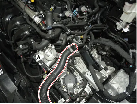
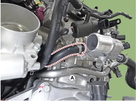
| 6. |
Disconnect the bypass hose (A).
|
| 7. |
Remove the water temperature control assembly (A) with the O-ring (B).
|


| 8. |
Install in the reverse order of removal. |
| 9. |
Fill the engine coolant. (Refer to Cooling System - "Coolant") |
| 10. |
Start engine and check for leaks. |
Components and components location Components 1. Radiator 2. Radiator upper mounting bracket 3. Radiator upper hose 4.
Components and components location Components 1. Water pump pulley 2. Water pump 3. Water pump gasket Repair procedures Removal and Installation 1.
Other information:
Kia Optima DL3 2019-2026 Service and Repair Manual: Mood Lamp Unit
Schematic diagrams Connector and Terminal function Repair procedures Removal When removing with a flat-tip screwdriver or remover, wrap protective tape around the tools to prevent damage to components.
Kia Optima DL3 2019-2026 Service and Repair Manual: Blower Resistor
Repair procedures Inspection 1. Measure the resistance between the terminals. 2. measured resistance is not within specification, the blower resistor must be replaced. (After removing the resistor) (1) Pin No 1.
Categories
- Manuals Home
- Kia Optima Owners Manual
- Kia Optima Service Manual
- Rear Brake Disc
- Body Electrical System
- Headlamps
- New on site
- Most important about car
