Kia Optima: Lighting System / Overhead Console Lamp
Kia Optima DL3 2019-2025 Service and Repair Manual / Body Electrical System / Lighting System / Overhead Console Lamp
Schematic diagrams
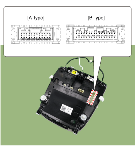
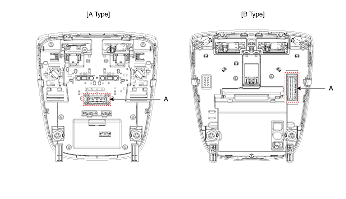
| Connector and Terminal Function |
| [A Type] |
|
Connector A |
||
|
|
||
|
Pin |
E xcept Russia Region |
Russia only |
|
Function |
Function |
|
|
1 |
Battery (+) |
Battery (+) |
|
2 |
IGN1 (PAB) |
- |
|
3 |
IGN1 (SBR) |
- |
|
4 |
eCall PWM |
- |
|
5 |
- |
- |
|
6 |
eCall botton |
eCall botton |
|
7 |
- |
- |
|
8 |
eCall ground |
eCall ground |
|
9 |
Ground (Room, Door lamp) |
Ground (Room, Door lamp) |
|
10 |
PAB ON |
- |
|
11 |
PAB OFF |
- |
|
12 |
Ground (PAB, SBR) |
- |
|
13 |
LED (Red) |
LED (Red) |
|
14 |
LED (Green) |
LED (Green) |
|
15 |
ACC |
- |
|
16 |
Botton back light |
Botton back light |
|
17 |
- |
- |
|
18 |
Door (-) |
Door (-) |
|
19 |
Room lamp signal |
Room lamp signal |
|
20 |
SBR (Rear left) |
- |
|
21 |
SBR (Rear center) |
- |
|
22 |
SBR (Rear Right) |
- |
|
23 |
Ground (eCall MCU) |
- |
|
24 |
Ground (eCall LED) |
Ground (eCall LED) |
| [B Type] |
|
Connector A |
||
|
|
||
|
Pin |
Except Russia Region |
R ussia only |
|
Function |
Function |
|
|
1 |
Battery (+) |
Battery (+) |
|
2 |
IGN1 (PAB) |
IGN1 (PAB) |
|
3 |
- |
- |
|
4 |
eCall PWM |
- |
|
5 |
- |
- |
|
6 |
eCall botton |
eCall botton |
|
7 |
- |
- |
|
8 |
IGN1 (ETCS) |
IGN1 (ETCS) |
|
9 |
Ground (PAB, SBR, TMU) |
Ground (PAB, SBR, TMU) |
|
10 |
- |
- |
|
11 |
- |
- |
|
12 |
eCall ground |
eCall ground |
|
13 |
Ground (Room, Door lamp) |
Ground (Room, Door lamp) |
|
14 |
PAB ON |
PAB ON |
|
15 |
PAB OFF |
PAB OFF |
|
16 |
Door (-) |
Door (-) |
|
17 |
LED (Red) |
LED (Red) |
|
18 |
LED (Green) |
LED (Green) |
|
19 |
ACC |
- |
|
20 |
Botton back light |
Botton back light |
|
21 |
IGN1 (SBR) |
IGN1 (SBR) |
|
22 |
Room lamp signal |
Room lamp signal |
|
23 |
- |
- |
|
24 |
- |
- |
|
25 |
SBR (Rear left) |
SBR (Rear left) |
|
26 |
SBR (Rear center) |
SBR (Rear center) |
|
27 |
SBR (Rear Right) |
SBR (Rear Right) |
|
28 |
Ground (eCall MCU) |
Ground (eCall MCU) |
|
29 |
Ground (eCall LED) |
Ground (eCall LED) |
|
30 |
- |
- |
|
31 |
- |
- |
|
32 |
- |
- |
Repair procedures
| Inspection |
| 1. |
Remove the overhead console lamp. (Refer to Lighting System - "Overhead Console Lamp") |
| 2. |
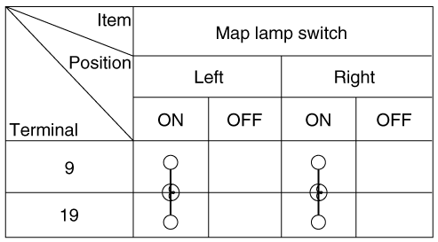
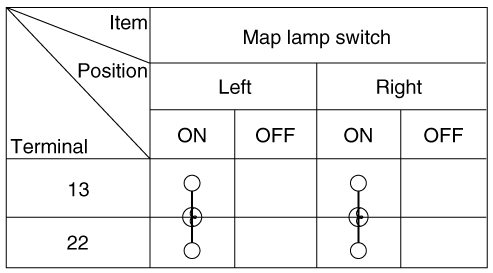
Check for continuity between terminals.
[A Type]
[B Type]
|
| Removal |
| 1. |
Disconnect the negative battery terminal. |
| 2. |
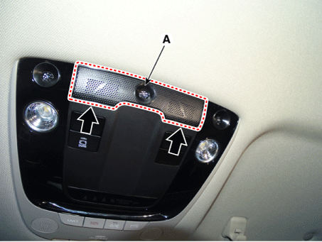
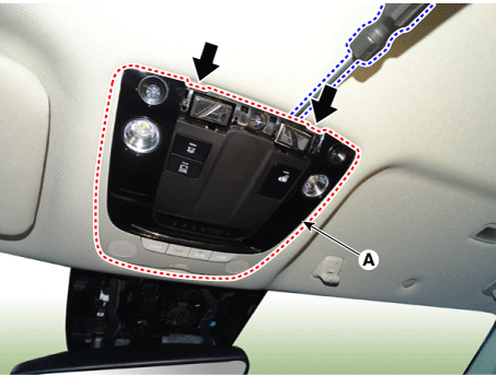
Remove the overhead console lamp mic grill (A) by using a flat-tip screwdriver or remover.
|
| 3. |
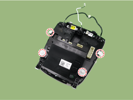
Remove the overhead console lamp (A) by using a flat-tip screwdriver or remover.
|
| 4. |
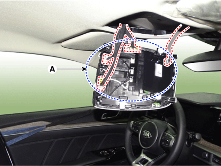
Disconnect the all connectors (A) from the overhead console lamp.
|
| Installation |
| 1. |
Install in the reverse of the removal. |
 Trunk Room Lamp
Repair procedures
Removal
1.
Disconnect the negative battery terminal.
2.
Remove the trunk room lamp (A) by pressing the hook.
...
 Rear Combination Lamp
Components and components location
Component Location
1. Tail lamp
2. Stop lamp
3. Tail/Stop lamp
4. Back up lamp
5. Turn signal lamp
Schema ...
Other information:
Kia Optima DL3 2019-2025 Service and Repair Manual: Underdrive Brake Control Solenoid Valve (UD/B_VFS)
Specifications Specification Item Specification Control type N/H (Normal High) Control pressure (kpa (kgf/cm², psi)) 0 - 1,569.06 (0 - 16, 0 - 227.57) Currency (mA) 0 - 1 ...
Kia Optima DL3 2019-2025 Owner's Manual: Checking tire inflation pressure
Check your tires once a month or more. Also, check the tire pressure of the spare tire. How to check Use a good quality gauge to check tire pressure. You can not tell if your tires are properly inflated simply by looking at them. Radial tires may look properly inflated even when they're under ...
Copyright © www.kioptima.com 2017-2025


