Kia Optima DL3: Lighting System / Trunk Room Lamp
Repair procedures
| Removal |
| 1. |
Disconnect the negative battery terminal. |
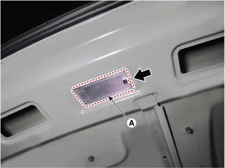
| 2. |
Remove the trunk room lamp (A) by pressing the hook.
|
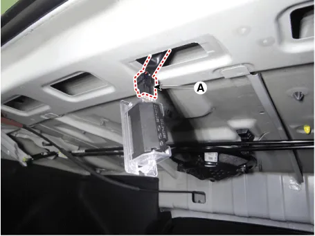
| 3. |
Disconnect the trunk room lamp connector (A).
|
| Installation |
| 1. |
Install in the reverse order of removal. |
| Replacement |
| 1. |
Remove the trunk room lamp. |
| 2. |
Remove the trunk room lamp cover (A).
|
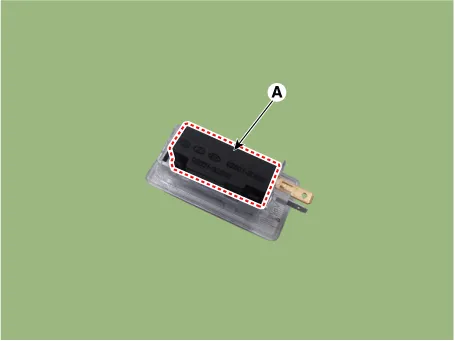
| 3. |
Replace the bulb (A).
|

Repair procedures Removal 1. Disconnect the negative battery terminal. 2. Remove the lcense lamp (A) by pressing the hook.
Schematic diagrams Connector and Terminal Function [A Type] Connector A Pin E xcept Russia Region Russia only Function Function 1 Battery (+) Battery (+) 2 IGN1 (PAB) - 3 IGN1 (SBR) - 4 eCall PWM - 5 - - 6 eCall botton eCall botton 7 - - 8 eCall ground eCall ground 9 Ground (Room, Door lamp) Ground (Room, Door lamp) 10 PAB ON - 11 PAB OFF - 12 Ground (PAB, SBR) - 13 LED (Red) LED (Red) 14 LED (Green) LED (Green) 15 ACC - 16 Botton back light Botton back light 17 - - 18 Door (-) Door (-) 19 Room lamp signal Room lamp signal 20 SBR (Rear left) - 21 SBR (Rear center) - 22 SBR (Rear Right) - 23 Ground (eCall MCU) - 24 Ground (eCall LED) Ground (eCall LED) [B Type] Connector A Pin Except Russia Region R ussia only Function Function 1 Battery (+) Battery (+) 2 IGN1 (PAB) IGN1 (PAB) 3 - - 4 eCall PWM - 5 - - 6 eCall botton eCall botton 7 - - 8 IGN1 (ETCS) IGN1 (ETCS) 9 Ground (PAB, SBR, TMU) Ground (PAB, SBR, TMU) 10 - - 11 - - 12 eCall ground eCall ground 13 Ground (Room, Door lamp) Ground (Room, Door lamp) 14 PAB ON PAB ON 15 PAB OFF PAB OFF 16 Door (-) Door (-) 17 LED (Red) LED (Red) 18 LED (Green) LED (Green) 19 ACC - 20 Botton back light Botton back light 21 IGN1 (SBR) IGN1 (SBR) 22 Room lamp signal Room lamp signal 23 - - 24 - - 25 SBR (Rear left) SBR (Rear left) 26 SBR (Rear center) SBR (Rear center) 27 SBR (Rear Right) SBR (Rear Right) 28 Ground (eCall MCU) Ground (eCall MCU) 29 Ground (eCall LED) Ground (eCall LED) 30 - - 31 - - 32 - - Repair procedures Inspection 1.
Other information:
Kia Optima DL3 2019-2026 Service and Repair Manual: Rear Combination Lamp
Components and components location Component Location 1. Tail lamp 2. Stop lamp 3. Tail/Stop lamp 4. Back up lamp 5. Turn signal lamp Schematic diagrams Connector and Terminal Function [A Type] Pin Function Center Ou
Kia Optima DL3 2019-2026 Service and Repair Manual: Condenser
Components and components location Components Location 1. Condenser Repair procedures Inspection 1. Check the condenser fins for clogging and damage. If clogged, clean them with water, and blow them with compressed air.
Categories
- Manuals Home
- Kia Optima Owners Manual
- Kia Optima Service Manual
- Timing Chain
- Identification Numbers
- Brake System
- New on site
- Most important about car
