Kia Optima DL3: Hydraulic System / Underdrive Brake Control Solenoid Valve (UD/B_VFS)
Specifications
Item
|
Specification
|
Control type
|
N/H (Normal High)
|
Control pressure (kpa (kgf/cm², psi))
|
0 - 1,569.06 (0 - 16, 0 - 227.57)
|
Currency (mA)
|
0 - 1,100
|
Coil resistance(Ω)
|
5.3 ± 0.3
|
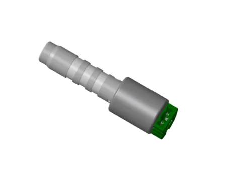
Description and operation
| • |
Underdrive brake control solenoid valve is a Variable Force Solenoid
(VFS) type.
|
| • |
When TCM supplies variable current to solenoid valve, hydraulic pressure
of underdrive brake is controlled by solenoid valve.
|
Underdrive brake control
solenoid valve operation table
|
UD/B_VFS
|
N/H
|
N, P
|
●
|
1
|
|
2
|
|
3
|
|
4
|
|
5
|
●
|
6
|
●
|
R
|
●
|
● : Connected status
Components and components location
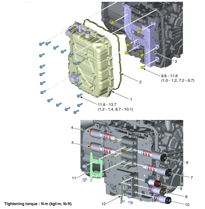
1. Valve Body Cover
|
8. SS-A ON/OFF Solenoid Valve
|
2. Valve Body Gasket
|
9. Torque Converter Control Solenoid
Valve
|
3. Main Harness
|
10. Line Pressure Control Solenoid
Valve
|
4. 26 Brake Control Solenoid
Valve
|
11. Support Bracket
|
5. 35R Clutch Control Solenoid
Valve
|
12. Support Bracket
|
6. Underdrive Brake Control Solenoid
Valve
|
|
7. Overdrive Clutch Control Solenoid
Valve
|
|
Repair procedures
| 1. |
The automatic transaxle system can be more quickly diagnosed for troubles
by using the vehicle diagnostic system (KDS).
KDS provides the following information.
| (1) |
Self diagnosis : Inspects and displays diagnostic trouble code
(DTC)
|
| (2) |
Sensor data : Checks the system input/output value status
|
| (3) |
Forced operation : Checks the system operating status
|
| (4) |
Additional function : Controls system options, zero point adjustment
and other functions
|
|
| 1. |
Switch "OFF" ignition.
|
| 2. |
Remove the air cleaner assembly.
(Refer to Engine Mechanical System - "Air cleaner")
|
| 3. |
Remove the battery and battery tray.
(Refer to Engine Electrical System - "Battery")
|
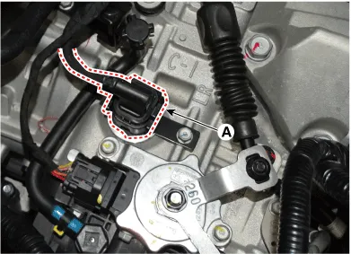
| 4. |
Disconnect the solenoid valve connector (A).
|
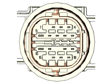
| 5. |
Measure the resistance between power terminal (5) and signal terminal
(16).
|
Specification : 5.3 ± 0.3 Ω
|
|
| • |
Automatic transaxle is composed of delicate components. Be careful
not to cause any damage on the component in the course of assembly
and disassembly.
|
| • |
Maintain clean condition so that foreign substance does not get
into the automatic transaxle.
|
| • |
Use a coated apron, latex gloves, and stainless tray to prevent
foreign substance from getting into the transaxle.
|
|
| 1. |
Remove the under cover.
(Refer to Engine Mechanical System - "Engine Room Under Cover")
|
| 2. |
Remove the ATF drain plug (A), allow the fluid to drain out and then
reinstall the drain plug.
|
Tightening torque:
33.3 - 43.1 N·m (3.4 - 4.4 kgf·m, 24.6 - 31.8 lb·ft)
|
| •
|
The existing ATF drain plug gasket must be replaced with
a new one. (Do not reuse it.
|
| •
|
Automatic transaxle fluid (ATF) can be reused. Collect
it using a clean 10-liter beaker.
|
|
|
| 3. |
Remove the air duct and air cleaner assembly.
(Refer to Engine Mechanical System - "Air cleaner")
|
| 4. |
Remove the fixing clip (A) and the air breather hose (B).
|
Tightening torque:
9.8 - 11.8 N·m (1.0 - 1.2 kgf·m, 7.2 - 8.7 lb·ft)
|
|
| 5. |
Separate the ATF cooler hose (A).
|
| 6. |
Lift the vehicle after loosening valve body cover upper bolts.
|
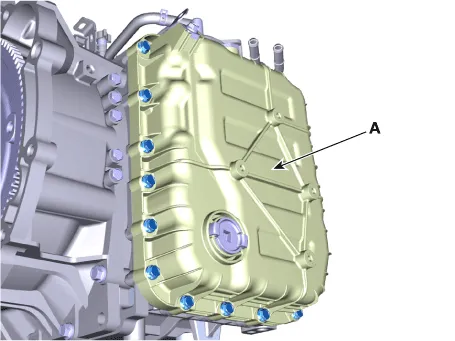
| 7. |
Remove the valve body cover (A) by loosening bolts.
|
Tightening torque:
11.8 - 13.7 N·m (1.2 - 1.4 kgf·m, 8.7 - 10.1 lb·ft)
|
|
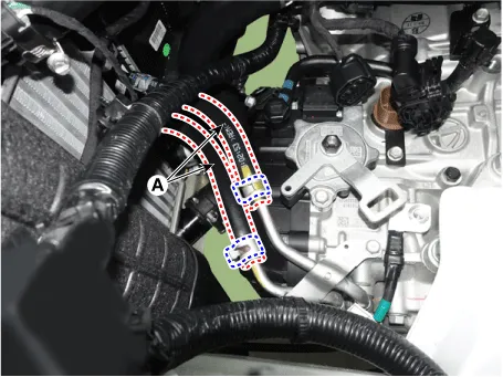
| 8. |
Remove the main harness (A) after removing the bolts.
|
Tightening torque:
9.8 - 11.8 N·m (1.0 - 1.2 kgf·m, 7.2 - 8.7 lb·ft)
|
|
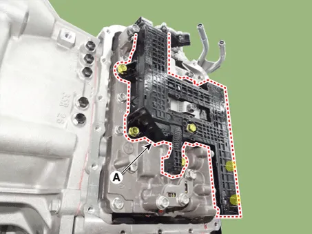
| 9. |
Remove solenoid valve support bracket (A) after loosening the bolts.
|
Tightening torque:
9.8 - 11.8 N·m (1.0 - 1.2 kgf·m, 7.2 - 8.7 lb·ft)
|
|
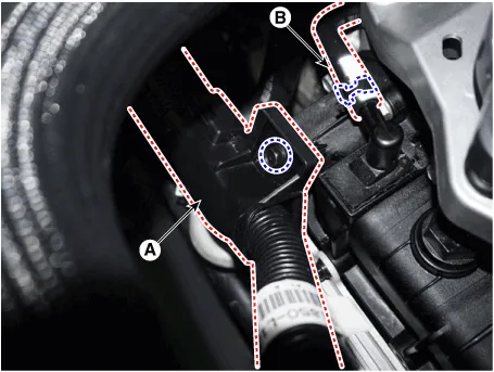
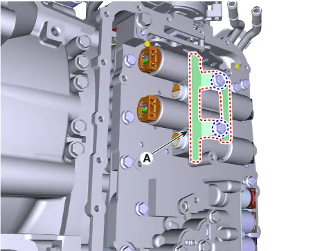
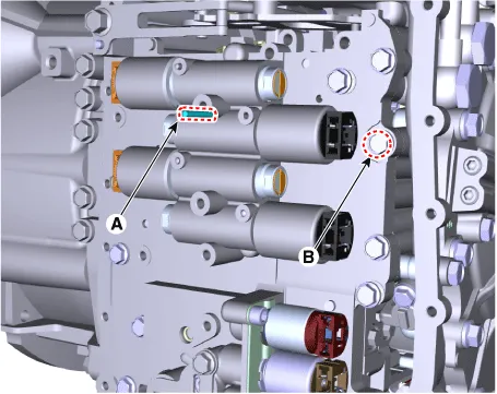
| 10. |
Remove the solenoid valve fixing pin (A) and loosen the valve body mounting
bolt (B).
|
Tightening torque:
9.8 - 11.8 N·m (1.0 - 1.2 kgf·m, 7.2 - 8.7 lb·ft)
|
|
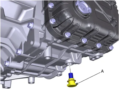
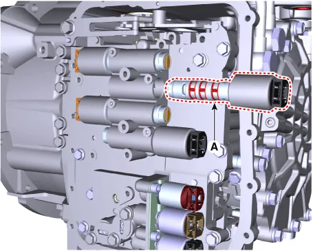
| 11. |
Remove the underdrive brake control solenoid valve (A).
|
| 1. |
Install in the reverse order of removal.
| •
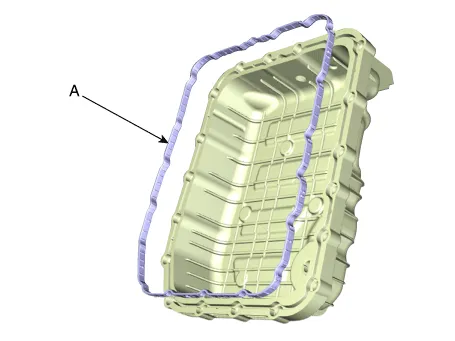
|
The existing valve body cover gasket (A) must be replaced
with a new one. (Do not reuse it.)
|
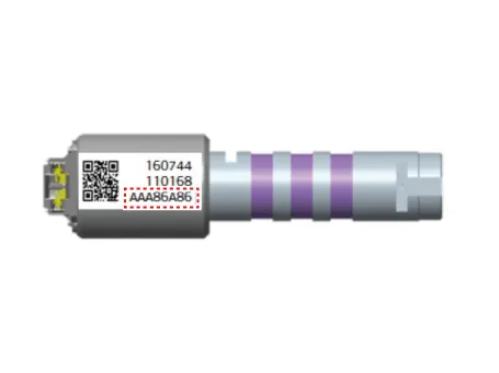
| •
|
Check the code (oil pressure characteristics value) at
the first before installing the solenoid valve.
|
|
|
| 2. |
Perform the procedures below after installing.
| (1) |
Refill the automatic transaxle with fluid.
(Refer to Hydraulic System - "Fluid")
|
| (2) |
Clear the diagnostic trouble codes (DTC) using the KDS. Disconnecting
the battery negative terminal will not clear the DTCs. Clear DTCs
using the KDS at all times.
|
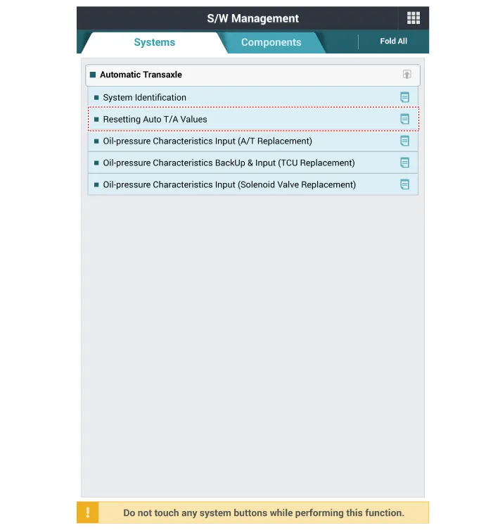
| (3) |
Reset the automatic transaxle adaptive values using the KDS.
|
| (4) |
Perform the oil pressure characteristics input procedure using
the KDS.
(Refer to Hydraulic System - "Oil pressure characteristics input")
|
| (5) |
Check for leakage of coolant or fluid from hose connection during
engine start.
|
| (6) |
Perform the TCM adaptive values learning procedure.
(Refer to Automatic Transaxle Control System - "Adjustment")
|
|
Specifications
Specification
Item
Specification
Control type
N/L (Normal Low)
Control pressure (kpa (kgf/cm², psi))
0 - 1,569.
Specifications
Specification
Item
Specification
Control type
N/H (Normal High)
Control pressure (kpa (kgf/cm², psi))
0 - 1,569.
Other information:
C
Repair procedures
Adjustment
Smart Key Code Saving
1.
Connect the VCI II in driver side crash pad lower panel, turn the power
on KDS.
2.
Select the vehicle model and then do "Smart key code saving".

