Kia Optima DL3: Power Door Mirrors / Power Door Mirror Actuator
Schematic diagrams
| Connector and Terminal Function |

Repair procedures
| Inspection |
| 1. |
Disconnect the negative battery terminal. |
| 2. |
Remove the front door trim. (Refer to Body - "Front Door Trim")
|

| 3. |
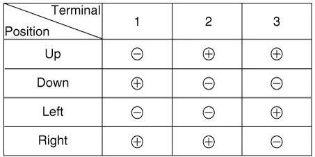
Apply battery voltage to each terminal as shown in the table and verify that the mirror operates properly. [Mirror Control]
[Mirror Heater]
[Side Repeater Lamp]
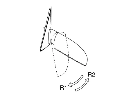
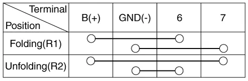
[Folding Mirror]
|


| Removal |
| 1. |
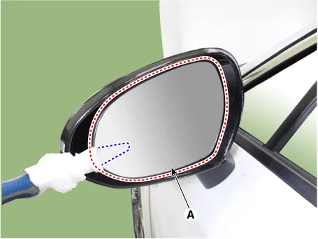
After inserting the flat-bladed screwdriver or remover as shown in the illustration below, remove the mirror (A) by applying a momentary force.
|

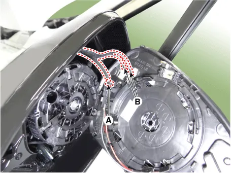
| 2. |
Disconnect the mirror heater connectors (A) and rear corner radar indicator connector (B).
|
| 3. |
Remove the mirror actuator (A) after loosening the mounting screw.
|

| 4. |
Disconnect the mirror actuator connector (A).
|

| Installation |
| 1. |
Install in the reverse order of removal. |
Schematic diagrams Connector and Terminal Function Pin Function 1 B-CAN (Low) 2 B-CAN (High) 3 Ground (Assist safety) 4 Assist safety 5 LIN (For IMS) 6 Battery (+) 7 IGN1 8 Driver safety 9 IMS Switch (For IMS) / Mirror Common (For Non IMS) 10 Mirror unfolding motor (Non IMS) 11 Mirror folding motor (Non IMS) 12 Mirror horizontal LH (Non IMS) 13 Mirror vertical LH (Non IMS) 14 Mirror vertical RH (Non IMS) 15 Mirror horizontal RH (Non IMS) 16 Ground Repair procedures Inspection Diagnosis With KDS 1.
Components and components location Component Location 1. Power window main switch 2. Rear window main switch 3.
Other information:
Kia Optima DL3 2019-2026 Service and Repair Manual: Keyless Entry And Burglar Alarm
Specifications Specification Item Specification Operating temperature 14 - 140°F (-10 - 60°C) RF Modulation FSK RF Frequency 433.
Kia Optima DL3 2019-2026 Service and Repair Manual: Temperature Control Actuator
Components and components location Components Location 1. Temperature control actuator [LH] 2. Temperature control actuator [RH] Description and operation Description The temperature control actuator is located at the heater unit.
Categories
- Manuals Home
- Kia Optima Owners Manual
- Kia Optima Service Manual
- Engine Mechanical System
- Engine Control / Fuel System
- Floor Console Assembly
- New on site
- Most important about car
