Kia Optima DL3: Body Electrical System / Power Door Mirrors
Components and components location
| Component Location |
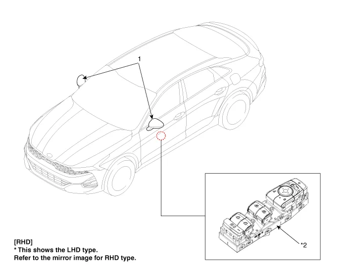
| 1. Power door mirror |
2. Power door mirror switch
|
Repair procedures Inspection When prying with a flat-tip screwdriver or use a prying trim tool, wrap it with protective tape, and apply protective tape around the related parts, to prevent damage.
Schematic diagrams Connector and Terminal Function Pin Function 1 B-CAN (Low) 2 B-CAN (High) 3 Ground (Assist safety) 4 Assist safety 5 LIN (For IMS) 6 Battery (+) 7 IGN1 8 Driver safety 9 IMS Switch (For IMS) / Mirror Common (For Non IMS) 10 Mirror unfolding motor (Non IMS) 11 Mirror folding motor (Non IMS) 12 Mirror horizontal LH (Non IMS) 13 Mirror vertical LH (Non IMS) 14 Mirror vertical RH (Non IMS) 15 Mirror horizontal RH (Non IMS) 16 Ground Repair procedures Inspection Diagnosis With KDS 1.
Other information:
Kia Optima DL3 2019-2026 Service and Repair Manual: Overhead Console Lamp
Schematic diagrams Connector and Terminal Function [A Type] Connector A Pin E xcept Russia Region Russia only Function Function 1 Battery (+) Battery (+)
Kia Optima DL3 2019-2026 Service and Repair Manual: In-car Sensor
Description and operation Description The In-car air temperature sensor is built in the heater & A/C control unit. The sensor contains a thermistor which measures the temperature of the inside. The signal decided by the resistance value which changes in accordance with perceived inside temperature, is delivered to heater co
Categories
- Manuals Home
- Kia Optima Owners Manual
- Kia Optima Service Manual
- Emergency trunk safety release
- Restraint
- Engine Control / Fuel System
- New on site
- Most important about car
