Kia Optima DL3: Power Door Mirrors / Power Door Mirror Switch
Schematic diagrams
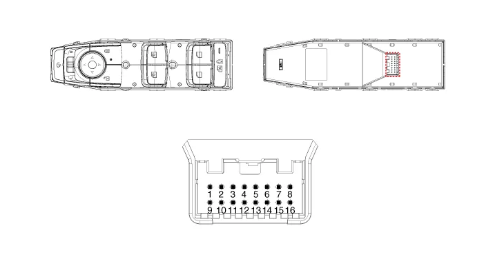
| Connector and Terminal Function |
|
Pin |
Function |
|
1 |
B-CAN (Low) |
|
2 |
B-CAN (High) |
|
3 |
Ground (Assist safety) |
|
4 |
Assist safety |
|
5 |
LIN (For IMS) |
|
6 |
Battery (+) |
|
7 |
IGN1 |
|
8 |
Driver safety |
|
9 |
IMS Switch (For IMS) / Mirror Common (For Non IMS) |
|
10 |
Mirror unfolding motor (Non IMS) |
|
11 |
Mirror folding motor (Non IMS) |
|
12 |
Mirror horizontal LH (Non IMS) |
|
13 |
Mirror vertical LH (Non IMS) |
|
14 |
Mirror vertical RH (Non IMS) |
|
15 |
Mirror horizontal RH (Non IMS) |
|
16 |
Ground |
Repair procedures
| Inspection |
Diagnosis With KDS
| 1. |
In the body electrical system, failure can be quickly diagnosed by using the vehicle diagnostic system (KDS). The diagnostic system (KDS) provides the following information.
|
| 2. |
Select the "Car model" and the 'DDM' to be checked in order to check the vehicle with the tester. |
| 3. |
Select the 'Current Data' menu to search the current state of the input/output data. |
| 4. |
To force actuate the input value of the module to be checked, select option 'Actuation Test'. |
| Removal |
| 1. |
Remove the power window main switch. (Refer to Power Windows - "Power Window Switch") |
| Installation |
| 1. |
Install in the reverse order of removal. |
Components and components location Component Location 1. Power door mirror 2. Power door mirror switch
Schematic diagrams Connector and Terminal Function Repair procedures Inspection 1. Disconnect the negative battery terminal.
Other information:
Kia Optima DL3 2019-2026 Service and Repair Manual: Trunk Room Lamp
Repair procedures Removal 1. Disconnect the negative battery terminal. 2. Remove the trunk room lamp (A) by pressing the hook. 3. Disconnect the trunk room lamp connector (A).
Kia Optima DL3 2019-2026 Service and Repair Manual: Wiper Arm
Repair procedures Removal 1. If necessary, remove the blade by pushing it in the direction arrow after opening the hook (A). • Move the windshield glass wiper blades to the servic
Categories
- Manuals Home
- Kia Optima Owners Manual
- Kia Optima Service Manual
- Headlamps
- Engine Mechanical System
- Engine Control Module (ECM)
- New on site
- Most important about car
