Kia Optima DL3: Automatic Transaxle Control System / Speed Sensor
Specifications
| Specification |
|
Item |
Specification |
|
Type |
Hall effect sensor |
|
Output voltage (V) |
High : 1.18 - 1.68 |
|
Low : 0.59 - 0.84 |
Description and operation
| Description |
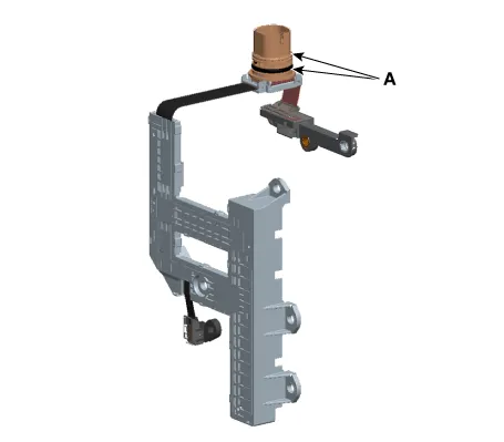
| Input Speed Sensor |
| • |
Input speed sensor (A) and output speed sensor (B) are integrated and installed in the transaxle.
|
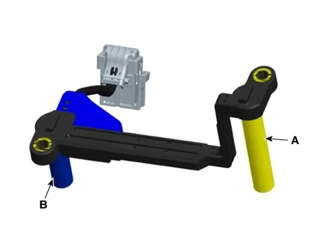
| • |
Speed sensor uses an electric current type hall sensor in which the current is changed by the magnetic variation. |
| • |
The sensor provides critical input data used in feedback control, engine clutch control, gear setting control, line pressure control, clutch activation pressure control, and sensor fault analysis. |
Components and components location
| Components |
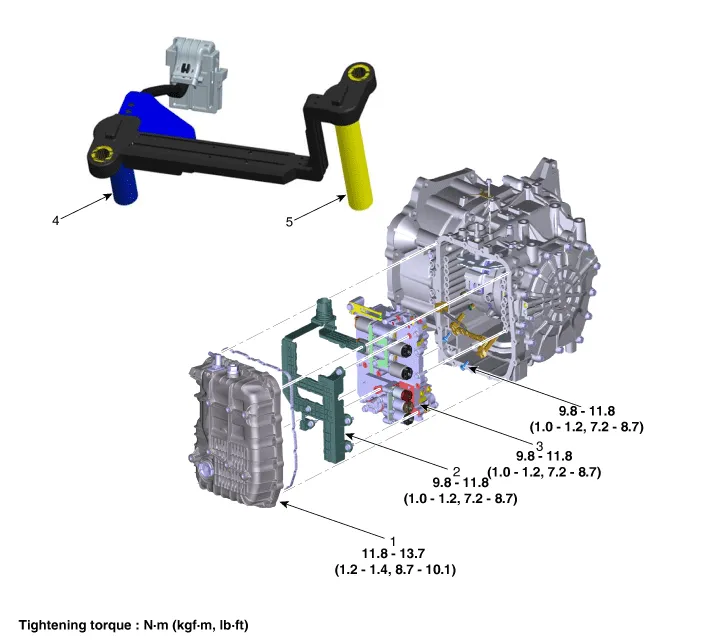
| 1. Valve Body Cover |
4. Output Speed Sensor |
| 2. Main Harness |
5. Input Speed Sensor |
| 3. Valve Body |
Repair procedures
| Inspection |
| 1. |
The automatic transaxle system can be more quickly diagnosed for troubles by using the vehicle diagnostic system (KDS). (Refer to "DTC guide") KDS provides the following information.
|
| Component inspection |
| 1. |
Check the sensor waveform with KDS. |
| Removal |
|

| 1. |
Remove the under cover. (Refer to Engine Mechanical System - "Engine Room Under Cover") |
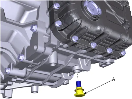
| 2. |
Remove the ATF drain plug (A), allow the fluid to drain out and then reinstall the drain plug.
|
| 3. |
Remove the air cleaner assembly. (Refer to Engine Mechanical System - "Air cleaner") |
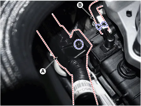
| 4. |
Remove the wiring bracket (A) and the air breather hose (B).
|
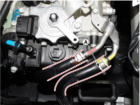
| 5. |
Disconnect the hose (A) after removing the automatic transaxle fluid cooler hose clamp.
|
| 6. |
Lift the vehicle after loosening valve body cover upper bolts. |
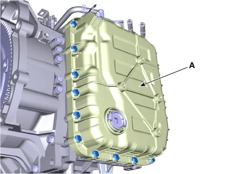
| 7. |
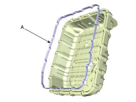
Remove the valve body cover (A) by loosening bolts.
|
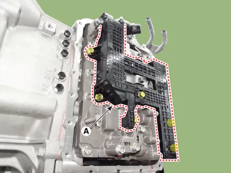
| 8. |
Remove the main harness (A) after removing the bolts.
|
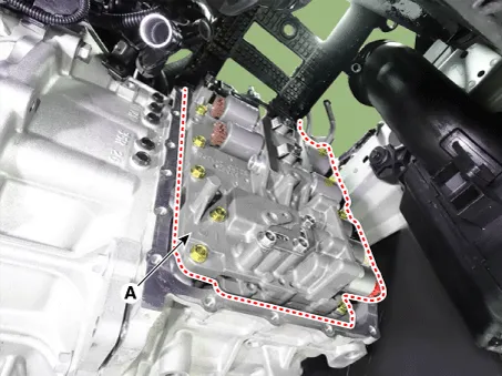
| 9. |
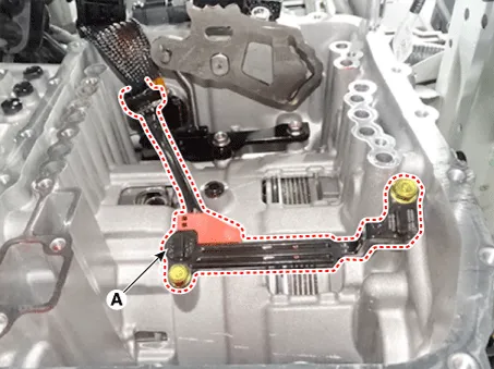
Remove the valve body assembly (A) after loosening the bolts.
|
| 10. |
Disconnect the speed sensor connector (A).
|

| 11. |
Remove the speed sensor (A) after loosening the bolts.
|
| Installation |
| 1. |
Install in the reverse order of removal.
|
Specifications Specification Item Specification Type *NTC thermistor Temp.
Specifications Specification Item Specification Power supply (V) 4.5 - 5.5 V Output type Shifting range (P/R/N/D) Non-contact(2 channel PWM signal) Start, Back-up lamp Contact Description and operation Description • The inhibitor switch mounted on the upper of transaxle and connected with shifter lever.
Other information:
Kia Optima DL3 2019-2026 Service and Repair Manual: Power Door Mirror Actuator
Schematic diagrams Connector and Terminal Function Repair procedures Inspection 1. Disconnect the negative battery terminal. 2. Remove the front door trim. (Refer to Body - "Front Door Trim") 3.
Kia Optima DL3 2019-2026 Service and Repair Manual: Cluster Ionizer
Components and components location Components Location 1. Condenser Description and operation Description The cluster ionizer makes disinfection and decomposition of bad smell from the air-conditioner or inflow air.
Categories
- Manuals Home
- Kia Optima Owners Manual
- Kia Optima Service Manual
- Suspension System
- Engine Control Module (ECM)
- Battery
- New on site
- Most important about car
