Kia Optima DL3: Automatic Transaxle System / Automatic Transaxle Control System
Description and operation
| Description |
Automatic transaxle control system relies on various measurements to determine the current control status and determine the necessary compensation values. These values are used to control the actuators and achieve the desired control output.
Operation

*T/CON_VFS : Torque converter control solenoid valve
*35R/C_VFS : 35R clutch control solenoid valve
*26/B_VFS : 26 Brake control solenoid valve
*UD/B_VFS : Underdrive brake control solenoid valve
*OD/C_VFS : Overdrive clutch control solenoid valve
*LINE_VFS : Line pressure control solenoid valve
*SS-A_ON/OFF : Shift control solenoid valve-A
Repair procedures
| Adjustment |
TCM adaptive values learning
| • |
TCM adaptive values learning : When shift shock has occurred or parts related with the transaxle has been replaced, TCM learning should be performed. |
| • |
In the following case, TCM learning is required. |
| – |
Automatic transaxle assembly replacement |
| – |
TCM upgrade or replacement |
| – |
Solenoid valve replacement |
TCM adaptive values learning procedure
| • |
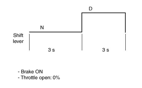
Static relearn (condition : ATF temperature 40 - 100°C (104 - 212°F) |
| 1) |
Step on the brake, and then pause for 3 seconds each on "N" range and "D" range. |
| 2) |
Repeat the above procedure four times.
|
| • |
Driving relearn |
| 1) |
Drive the vehicle through all the gears (1st → 2nd → 3rd → 4th → 5th → 6th).
|

| 2) |
Decelerate the vehicle by stepping on the brake (6th → 5th → 4th → 3rd → 2nd → 1st). |
| 3) |
Repeat the above procedure four times. |
- Transaxle Control Module (TCM)
- Transaxle Oil Temperature Sensor (Main Harness)
- Speed Sensor
- Inhibitor Switch
- Shift Lever
- Shift Cable
Service data Service data Automatic Transaxle Item Specification Transaxle model A6MF1-2 Engine model G 2.
Description and operation Description The module receives and processes signals from various sensors and implements a wide range of transaxle controls to ensure optimal driving conditions for the driver.
Other information:
Kia Optima DL3 2019-2026 Service and Repair Manual: Rear Glass Defogger
C
Kia Optima DL3 2019-2026 Service and Repair Manual: Smart Key System
Specifications Specifications Smart Key Unit Items Specification Rated voltage DC 12 V Operation voltage DC 9 - 16 V Operation temperature -40 to 185°F (-40 to 85°C) RF Receiver Items
Categories
- Manuals Home
- Kia Optima Owners Manual
- Kia Optima Service Manual
- Charging System
- Floor Console Assembly
- Headlamps
- New on site
- Most important about car
