Kia Optima DL3: Automatic Transaxle Control System / Transaxle Oil Temperature Sensor (Main Harness)
Specifications
Item
|
Specification
|
Type
|
*NTC thermistor
|
Temp.[(°C)°F] / Resistance (kΩ)
|
(-40)-40 / 48.1
|
(-20)-4.0 / 15.6
|
(0)32.0 / 5.88
|
(20)68.0 / 2.51
|
(40)104.0 / 1.19
|
(60)140.0 / 0.61
|
(80)176.0 / 0.32
|
(100)212.0 / 0.18
|
(120)248.0 / 0.10
|
(140)284.0 / 0.06
|
(150)302.0 / 0.05
|
*NTC : Negative Temperature Coefficient
Description and operation
| • |
The sensor used is a thermistor (NTC) in which resistance changes with
temperature variation.
|
| • |
When the TCM supplies about 5 V of power to sensor, the sensor output
value changes depending on ATF temperature.
|
| • |
Oil temperature sensor is installed on the valve body integrated with
a main harness module.
|
Functions
| • |
Transaxle oil temperature sensor monitors the temperature of ATF and
conveys the readings to TCM.
|
| • |
Data produced by this sensor is used to identify torque converter clutch
activation and deactivation zones within the low temperature and high temperature
range and to compensate hydraulic pressure levels during gear changes.
|
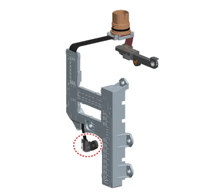
Components and components location
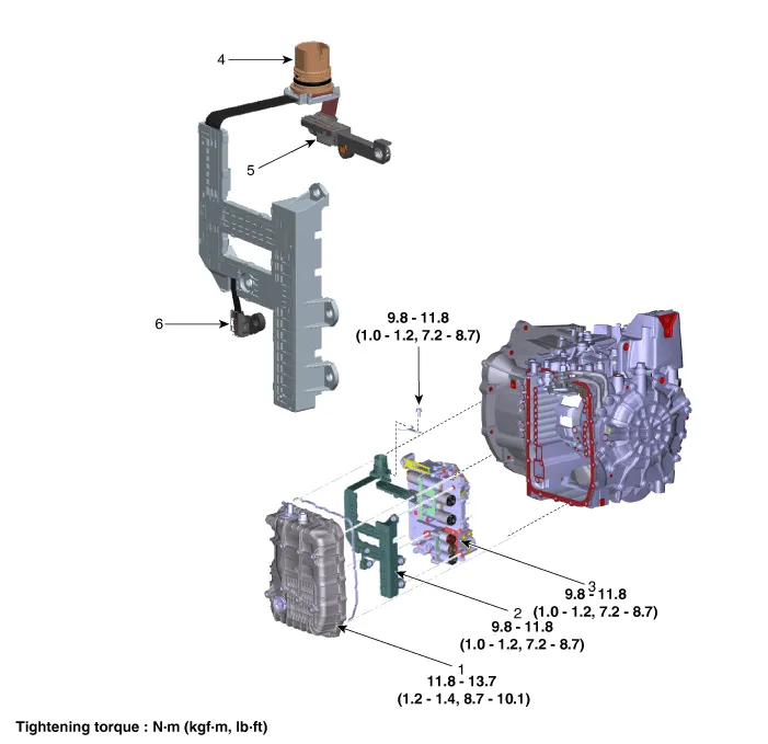
1. Valve Body Cover
|
4. Main Connector
|
2. Main Harness
|
5. Speed Sensor Connector
|
3. Valve Body
|
6. Oil Temperature Sensor
|
Repair procedures
| 1. |
The automatic transaxle system can be more quickly diagnosed for troubles
by using the vehicle diagnostic system (KDS). (Refer to "DTC guide")
KDS provides the following information.
| (1) |
Self diagnosis : Inspects and displays diagnostic trouble code
(DTC)
|
| (2) |
Sensor data : Checks the system input/output value status
|
| (3) |
Forced operation : Checks the system operating status
|
| (4) |
Additional function : Controls system options, zero point adjustment
and other functions
|
|
| 1. |
Check the resistance by using the KDS.
Item
|
Specification
|
Temp.[(°C)°F] / Resistance (kΩ)
|
(-40)-40 / 48.1
|
(-20)-4.0 / 15.6
|
(0)32.0 / 5.88
|
(20)68.0 / 2.51
|
(40)104.0 / 1.19
|
(60)140.0 / 0.61
|
(80)176.0 / 0.32
|
(100)212.0 / 0.18
|
(120)248.0 / 0.10
|
(140)284.0 / 0.06
|
(150)302.0 / 0.05
|
|
| • |
Automatic transaxle is composed of delicate components. Be careful
not to cause any damage on the component in the course of assembly
and disassembly.
|
| • |
Maintain clean condition so that foreign substance does not get
into the automatic transaxle.
|
| • |
Use a coated apron, latex gloves, and stainless tray to prevent
foreign substance from getting into the transaxle.
|
|
| 1. |
Remove the under cover.
(Refer to Engine Mechanical System - "Engine Room Under Cover")
|
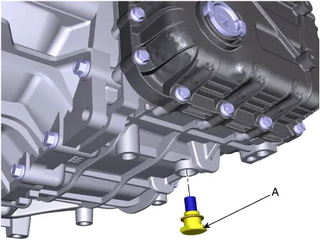
| 2. |
Remove the ATF drain plug (A), allow the fluid to drain out and then
reinstall the drain plug.
|
Tightening torque:
33.3 - 43.1 N·m (3.4 - 4.4 kgf·m, 24.6 - 31.8 lb·ft)
|
| •
|
The existing ATF drain plug gasket must be replaced with
a new one. (Do not reuse it.)
|
| •
|
Automatic transaxle fluid (ATF) can be reused. Collect
it using a clean 10-liter beaker.
|
|
|
| 3. |
Remove the air duct and air cleaner assembly.
(Refer to Engine Mechanical System - "Air cleaner")
|
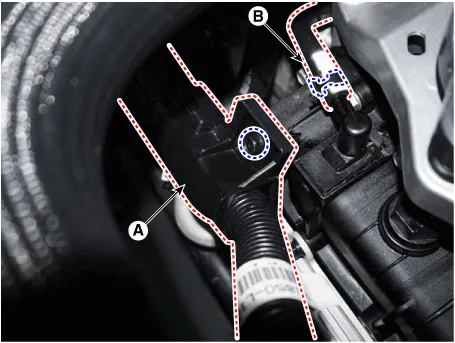
| 4. |
Remove the wiring bracket (A) and the air breather hose (B).
|
Tightening torque:
9.8 - 11.8 N·m (1.0 - 1.2 kgf·m, 7.2 - 8.7 lb·ft)
|
|
| 5. |
Disconnect the hose (A) after removing the automatic transaxle fluid
cooler hose clamp.

|
| 6. |
Lift the vehicle after loosening valve body cover upper bolts.
|
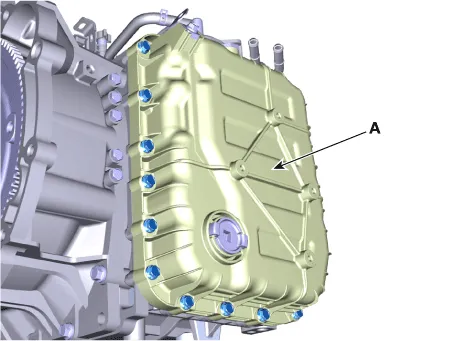
| 7. |
Remove the valve body cover (A) by loosening bolts.
|
Tightening torque:
11.8 - 13.7 N·m (1.2 - 1.4 kgf·m, 8.7 - 10.1 lb·ft)
|
|
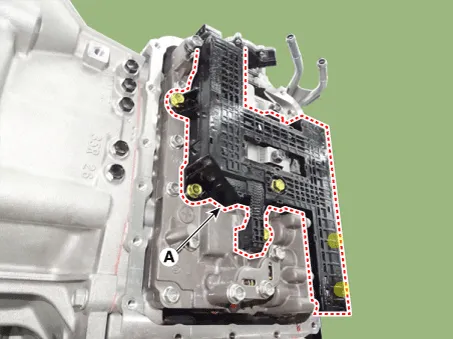
| 8. |
Remove the main harness (A) after removing the bolts.
|
Tightening torque:
9.8 - 11.8 N·m (1.0 - 1.2 kgf·m, 7.2 - 8.7 lb·ft)
|
|
| 9. |
Remove the valve body assembly (A) after loosening the bolts.
|
Tightening torque:
9.8 - 11.8 N·m (1.0 - 1.2 kgf·m, 7.2 - 8.7 lb·ft)
|

|
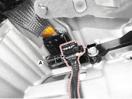
| 10. |
Disconnect the speed sensor connector (A).
|
| 11. |
Loosen the main harness bolt (A).
|
Tightening torque :
9.8 - 11.8 N·m (1.0 - 1.2 kgf·m, 7.2 - 8.7 lb·ft)
|
|
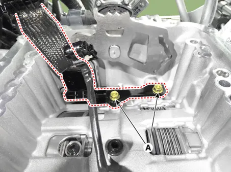
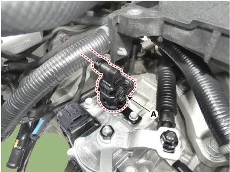
| 12. |
Disconnect the solenoid valve connector (A).
|
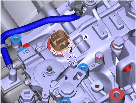
| 13. |
Remove the solenoid valve connector mounting clip (A).
|
Tightening torque:
9.8 - 11.8 N·m (1.0 - 1.2 kgf·m, 7.2 - 8.7 lb·ft)
|
|
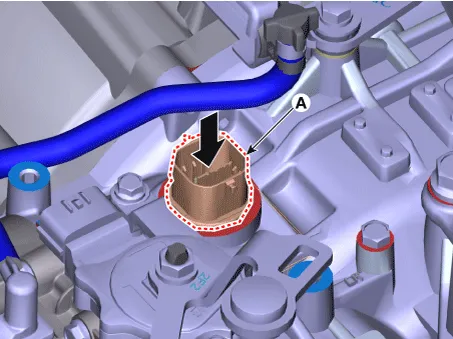
| 14. |
Remove the solenoid valve connector (A) by pushing down from the transaxle.
|
| 1. |
Install in the reverse order of removal.
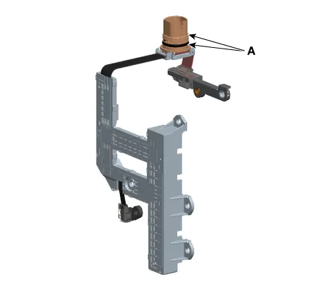
| •
|
Before installing the connector, apply the ATF to the
O-ring.
|
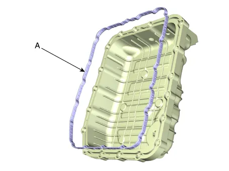
| •
|
The existing valve body cover gasket (A) must be replaced
with a new one. (Do not reuse it.)
|
| •
|
Check fluid level, after filling the automatic transaxle
with fluid.
(Refer to Hydraulic System - "Fluid")
|
| •
|
After installing, check for leakage of coolant or fluid
from hose connection during engine start.
|
|
|
Description and operation
Description
The module receives and processes signals from various sensors and implements
a wide range of transaxle controls to ensure optimal driving conditions for the
driver.
Specifications
Specification
Item
Specification
Type
Hall effect sensor
Output voltage (V)
High : 1.
Other information:
Repair procedures
Removal
1.
Disconnect the negative battery terminal.
2.
Remove the roof trim assembly.
(Refer to Body - "Roof Trim Assembly")
3.
Disconnect the high mounted stop lamp connector (A).
Schematic diagrams
Connector and Terminal Function
Pin
Function
Connector A
Connector B
Connector C
Connector D
1
-
Front washer switch (Output)
-
Driver outside handle switch (Input)

