Kia Optima DL3: Front Suspension System / Sub Frame
Repair procedures
| Removal |
| 1. |
Disconnect the (-) battery terminal. |
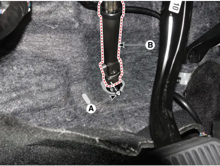
| 2. |
Loosen the bolt (A) and remove the universal joint (B).
|

| 3. |
Remove the front wheel and tire. (Refer to Tires/Wheels - "Wheel") |
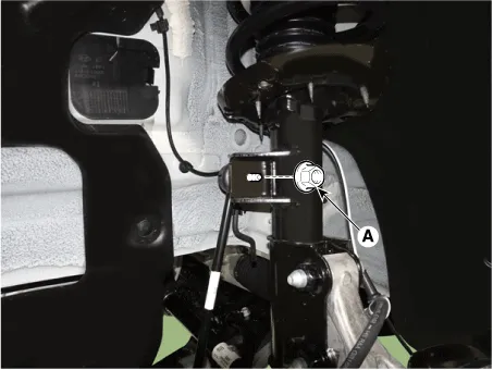
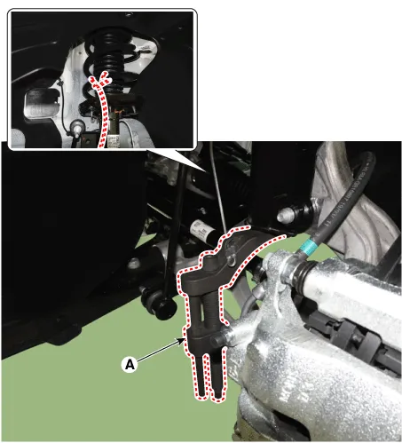
| 4. |
Disconnect the stabilizer link with the front strut assembly after loosening the nut (A).
|
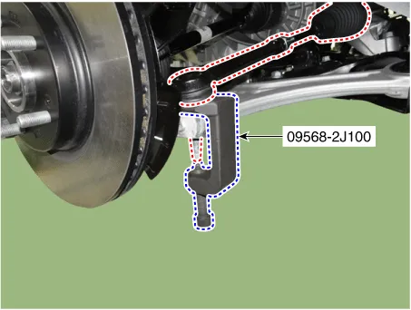
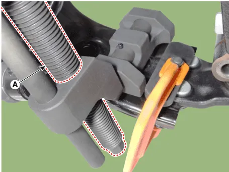
| 5. |
Disconnect the tie rod end ball joint from the knuckle by using the SST (09568-2J100).
|

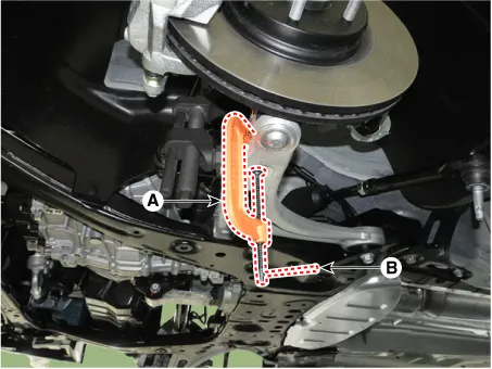
| 6. |
Loosen the lower arm mounting nut (A).
|
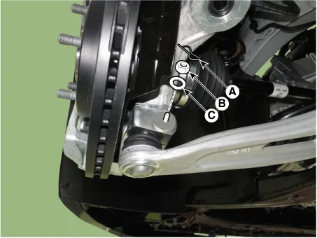
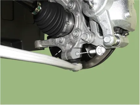
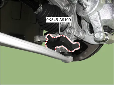
| 7. |
Disconnect lower arm ball joint from the knuckle by using the SST (0K545-A9100).
|
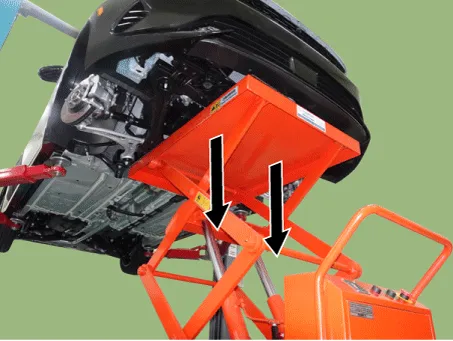
| 8. |
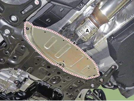
Remove the engine room under cover. G 2.0 NU MPI (Refer to Engine Mechanical System - "Engine Room Under Cover") G 2.5 GDI THETA II (Refer to Engine Mechanical System - "Engine Room Under Cover") |
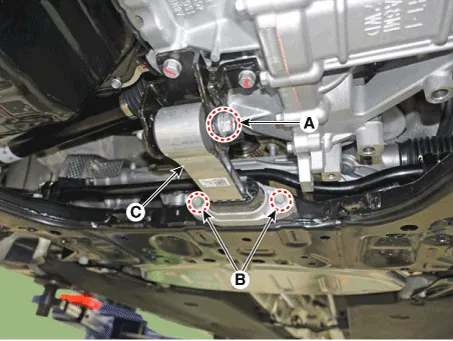
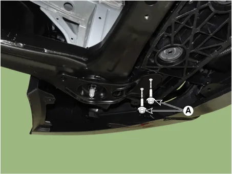
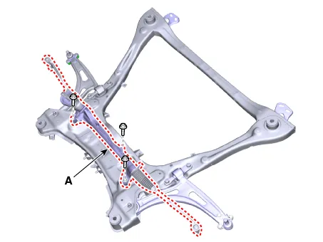
| 9. |
Separate the roll rod bracket (C) after loosening the bolts (A), (B).
|
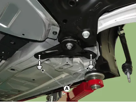
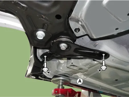
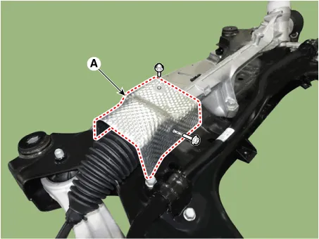
| 10. |
Remove the heat protector (A).
|
| 11. |
Remove the muffler rubber hanger (A).
|

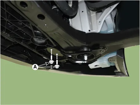
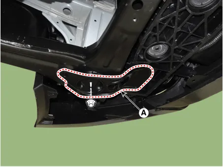
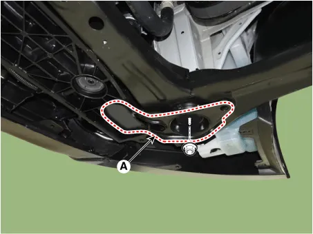
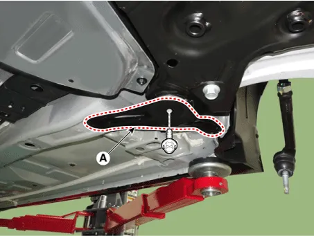
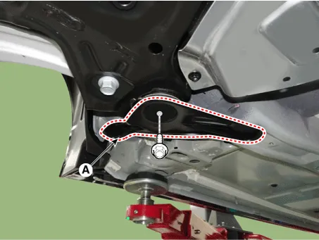
| 12. |
Remove the fasner (A).
|

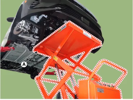
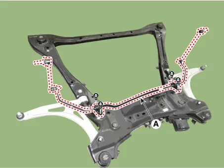
| 13. |
Remove the sub frame.
|


| 14. |
Loosen the bolts and remove the steering gear box heat protector (A).
|
| 15. |
Remove the steering gearbox (A) from the front sub frame by loosening the mounting bolts.
|
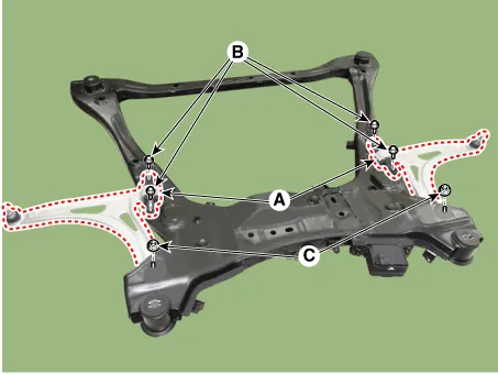
| 16. |
Loosen the mounting bolts and then remove the stabilizer bar (A).
|
| 17. |
Remove the lower arm (A).
|
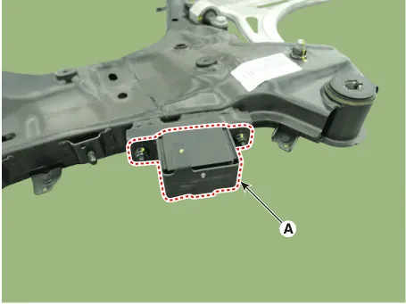
| 18. |
Remove the dynamic damper (A).
|
Repair procedures Removal 1. Disconnect the (-) battery terminal. 2. Remove the front wheel and tire.
Components and components location Components and Components Location 1. Trailing arm 2. Rear shock absorber 3. Rear suspension 4.
Other information:
Kia Optima DL3 2019-2026 Service and Repair Manual: Vanity Lamp
Repair procedures Removal When removing with a flat-tip screwdriver or remover, wrap protective tape around the tools to prevent damage to components. 1.
Kia Optima DL3 2019-2026 Service and Repair Manual: Rear Glass Defogger Printed Heater
Repair procedures Inspection • Wrap tin foil around the end of the voltmeter test lead to prevent damaging the heater line. Apply pressure on the tin foil with hand and move the tin foil along the grid line to check for open circ
Categories
- Manuals Home
- Kia Optima Owners Manual
- Kia Optima Service Manual
- Front Axle Assembly
- Charging System
- Lift And Support Points
- New on site
- Most important about car
