Kia Optima DL3: Suspension System / Rear Suspension System
Components and components location
| Components and Components Location |
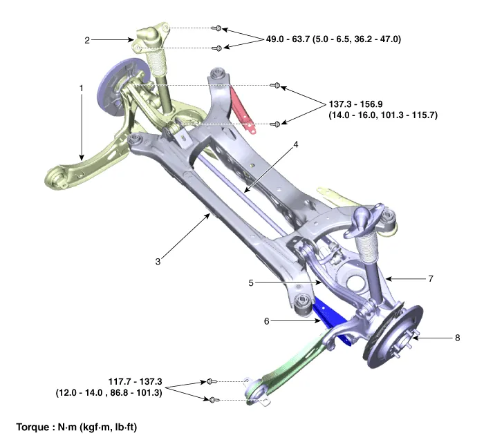
| 1. Trailing arm 2. Rear shock absorber 3. Rear suspension 4. Rear stabilizer bar |
5. Rear upper arm 6. Rear assist arm 7. Rear lower arm 8. Rear axle assembly |
- Rear Shock Absorber
- Rear Coil Spring
- Rear Upper Arm
- Rear Lower Arm
- Rear Assist Armature
- Trailing Arm
- Rear Stabilizer Bar
- Rear sub frame
Repair procedures Removal 1. Disconnect the (-) battery terminal. 2. Loosen the bolt (A) and remove the universal joint (B).
Components and components location Components Repair procedures Removal 1. Disconnect the (-) battery terminal.
Other information:
Kia Optima DL3 2019-2026 Service and Repair Manual: Integrated Memory Seat (IMS) Unit
Specifications Specifications Item Specifications Rated voltage DC 12 V Operating voltage DC 9 - 16 V Operating temperature range -22 to 167°F (-30 to 75°C) Dark current Max.
Kia Optima DL3 2019-2026 Service and Repair Manual: Wiper Arm
Repair procedures Removal 1. If necessary, remove the blade by pushing it in the direction arrow after opening the hook (A). • Move the windshield glass wiper blades to the servic
Categories
- Manuals Home
- Kia Optima Owners Manual
- Kia Optima Service Manual
- Headlamps
- Body (Interior and Exterior)
- Identification Numbers
- New on site
- Most important about car
