Kia Optima DL3: Engine Control System / Variable Intake Solenoid (VIS) Valve
Specifications
| Specification |
|
Item |
Specification |
|
Coil resistance (Ω) |
30.0 - 35.0 [22°C (71.6°F)] |
Description and operation
| Description |
| • |
The Variable Intake Solenoid (VIS) valve controls the vacuum modulator which activates a valve in the intake manifold. |
| • |
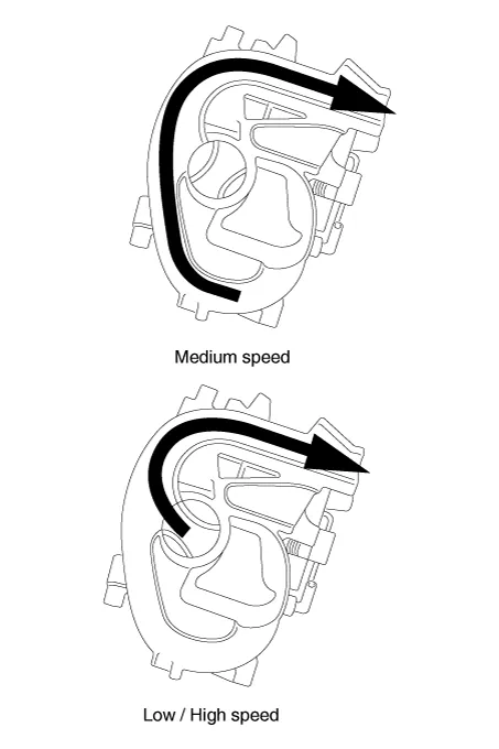
The ECM opens or closes this valve according to engine condition (Refer to below table). |
|
Engine condition |
VIS valve |
Operation |
|
Medium speed |
Closed |
Increasing engine performance in low engine speed by reducing intake interference
among cylinders |
|
Low / High speed |
Open |
Minimizing intake resistance by shortening intake manifold length and increasing
area of air entrance |
Components and components location
| Components Location |
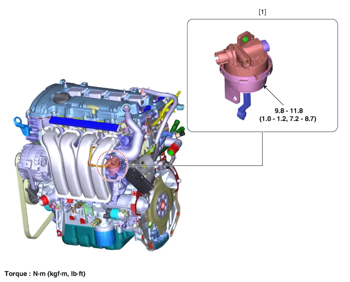
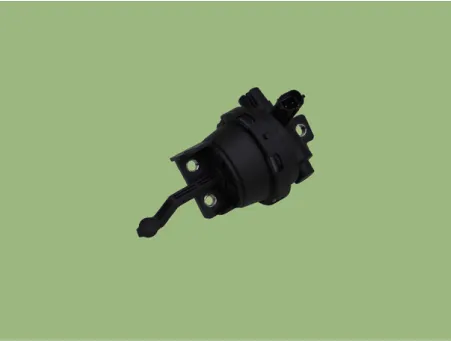
| 1. Variable Intake Solenoid (VIS)
Valve |
Schematic diagrams
| Circuit Diagram |
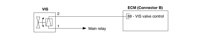
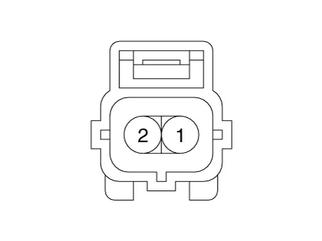
Harness Connector
Repair procedures
| Inspection |
| 1. |
The engine control system can be more quickly diagnosed for troubles by using the vehicle diagnostic system (KDS). (Refer to "DTC guide") KDS provides the following information.
|
| Component Inspection |
| 1. |
Turn the ignition switch OFF. |
| 2. |
Disconnect the VIS valve connector. |
| 3. |
Measure resistance between VIS valve terminals 1 and 2.
|
| Removal |
| 1. |
Disconnect the negative battery terminal. |
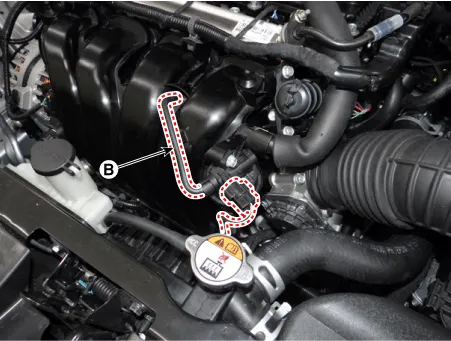
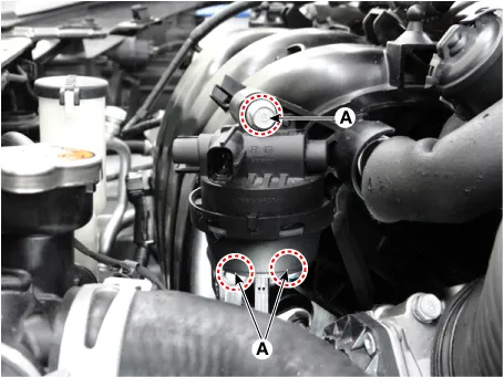
| 2. |
Disconnect the variable intake solenoid valve connector (A) and vacuum hose (B).
|
| 3. |
Remove the VIS valve after loosening the mounting bolts (A).
|
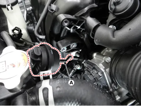
| 4. |
Remove the VIS valve (A) after loosening the rod.
|
| Installation |
|

| 1. |
Install in the reverse order of removal. |
Specifications Specification Item Specification Coil Resistance (Ω) 9.4 - 10.4 [20°C(68°F)] Description and operation Description • Continuous Variable Valve Timing (CVVT) system advances or retards the valve timing of the intake and exhaust valve in accordance with the ECM control signal which is calculated by the engine speed and load.
Description and operation Description • The Variable Charge Motion Actuator (VCMA) is installed on the inlet of the intake manifold.
Other information:
Kia Optima DL3 2019-2026 Service and Repair Manual: Power Door Locks
C
Kia Optima DL3 2019-2026 Service and Repair Manual: Power Windows
Components and components location Component Location 1. Power window main switch 2. Rear window main switch 3. Front power window motor 4. Rear power window motor Description and operation Description Power Window Safety Function When the driver or passenger p
Categories
- Manuals Home
- Kia Optima Owners Manual
- Kia Optima Service Manual
- Lift And Support Points
- Emergency trunk safety release
- Low tire pressure position telltale
- New on site
- Most important about car
