Kia Optima DL3: Wiper/Washer / Washer Motor
Repair procedures
| Inspection |
Washer Motor
| 1. |
With the washer motor connected to the reservoir tank, fill the reservoir tank with water.
|

| 2. |
Connect positive (+) battery cables to terminal 2 and negative (-) battery cables to terminal 1 respectively. |
| 3. |
Check that the motor operates normally and the washer motor runs and water sprays from the front nozzles. |
| 4. |
If they are abnormal, replace the washer motor.
|

Washer Fluid Level Sensor
| 1. |
Disconnect the negative battery terminal. |
| 2. |
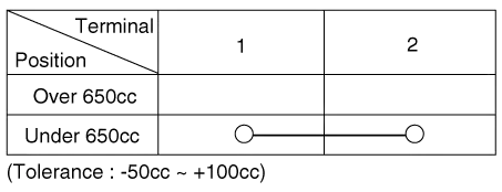
Drain the washer fluid less than 650 cc. |
| 3. |
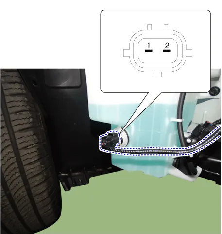
Check for continuity between the No. 1 and No.2 terminal in each float position. There should be continuity when the float is down. There should be no continuity when the float is up. |
| 4. |
If the continuity is not as specified, replace the washer fluid level switch
|
| Removal |
Washer Motor
| 1. |
Disconnect the negative battery terminal. |
| 2. |
Remove the engine room under cover. G 2.0 NU MPI (Refer to Engine Mechanical System - "Engine Room Under Cover") G 2.5 GDI THETA II (Refer to Engine Mechanical System - "Engine Room Under Cover") |
| 3. |
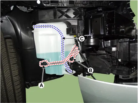
Disconnect the connector (B) and then remove the washer motor (C) after separating the nozzles (A).
|

Washer Fluid Level Sensor
| 1. |
Disconnect the negative battery terminal. |
| 2. |
Remove the engine room under cover. G 2.0 NU MPI (Refer to Engine Mechanical System - "Engine Room Under Cover") G 2.5 GDI THETA II (Refer to Engine Mechanical System - "Engine Room Under Cover") |
| 3. |
Remove the washer fluid level sensor (A) after disconnecting the connector (B).
|

Reservoir
| 1. |
Disconnect the negative battery terminal. |
| 2. |
Remove the engine room under cover. G 2.0 NU MPI (Refer to Engine Mechanical System - "Engine Room Under Cover") G 2.5 GDI THETA II (Refer to Engine Mechanical System - "Engine Room Under Cover") |
| 3. |
Remove the right side front wheel guard. (Refer to Body - "Front Wheel Guard") |
| 4. |
Remove the reservoir.
|

| Installation |
| 1. |
Install in the reverse order of the removal. |
Repair procedures Replacement 1. If wiper switch needs to be replaced, replace the multifunction switch assembly. (Refer to Body Electrical System - "Multifunction Switch")
Schematic diagrams Connector and Terminal Function
Other information:
Kia Optima DL3 2019-2026 Service and Repair Manual: Power Door Mirrors
C
Kia Optima DL3 2019-2026 Service and Repair Manual: Smart Key Unit
Schematic diagrams Connector and Terminal Function Pin Function Connector A Connector B Connector C Connector D 1 - Front washer switch (Output) - Driver outside handle switch (Input)
Categories
- Manuals Home
- Kia Optima Owners Manual
- Kia Optima Service Manual
- Motor Driven Power Steering
- Brake System
- Headlamps
- New on site
- Most important about car
