Kia Optima DL3: Automatic Transaxle System / Automatic Transaxle System
Components and components location
| Components |
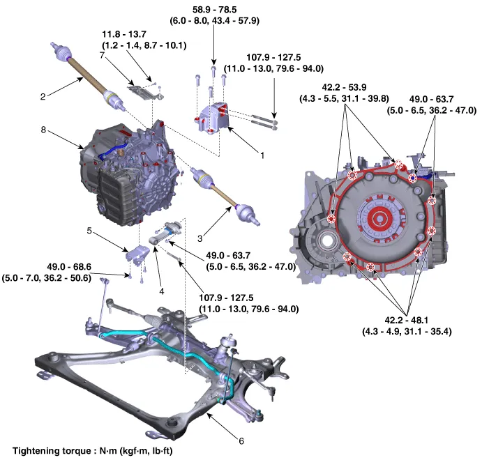
| 1. Transaxle Support Braket
|
5. Roll Rod Support Bracket
|
| 2. Driveshaft Assembly [RH]
|
6. Sub Frame |
| 3. Driveshaft Assembly [LH]
|
7. Driveshaft Heat Protector
|
| 4. Roll Rod Bracket |
8. Automatic Transaxle Assembly
|
Repair procedures
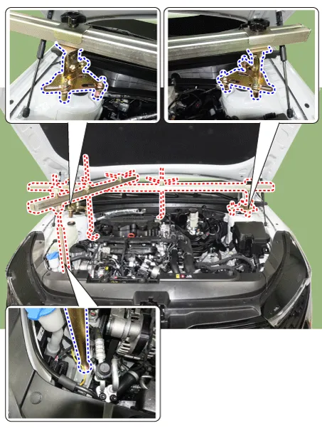
| Removal |
| 1. |
Remove the air cleaner assembly. (Refer to Engine Mechanical System - "Air cleaner") |
| 2. |
Remove the battery and battery tray. (Refer to Engine Electrical System - "Battery") |
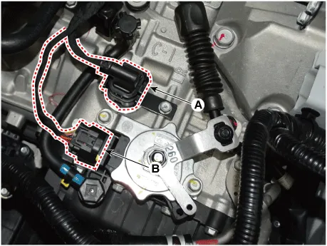
| 3. |
Disconnect the main connector (A) and inhibitor switch connector (B).
|
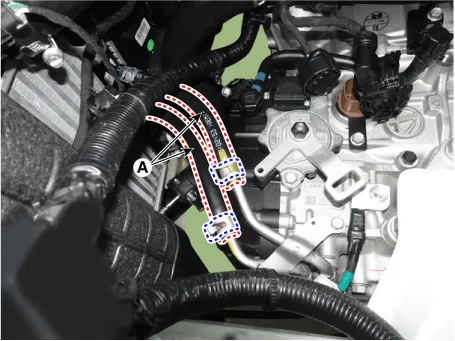
| 4. |
Remove the wiring fixing clips (A) from the brackets.
|
| 5. |
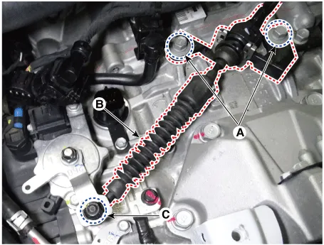
Remove the wiring protector (A) by loosening the bolt.
|
| 6. |
Remove the shift cable (B) after loosening the nut (C) and bolts (A).
|
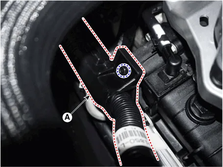
| 7. |
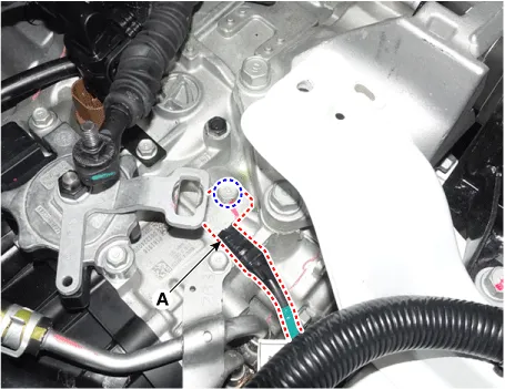
Remove the ground line after removing the bolt (A).
|
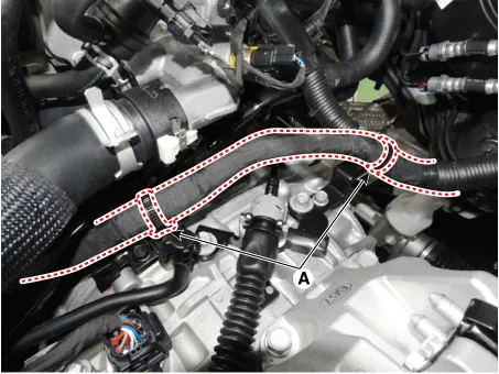
| 8. |
Separate the ATF cooler hose (A).
|
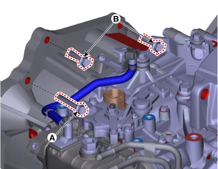
| 9. |
Loosen the starter mounting bolt (A) and transaxle mounting bolts (B).
|
| 10. |
Assemble the engine support fixture on the engine room. (Refer to Special Service Tools - "Engine support fixture assembly drawing")
|
| 11. |
Remove the under cover. (Refer to Engine Mechanical System - "Engine Room Under Cover") |
| 12. |
Support the transaxle safely with a jack.
|
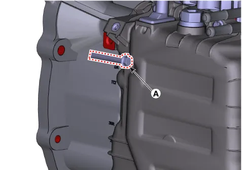
| 13. |
Remove the cover (A).
|
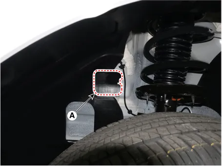
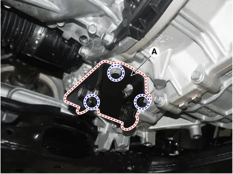
| 14. |
Remove the automatic transaxle support bracket mounting bolts (A).
|
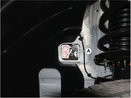
| 15. |
Remove the automatic transaxle support bracket (A).
|

| 16. |
Remove the drive shaft assembly. (Refer to Driveshaft and Axle - "Front Driveshaft") |
| 17. |
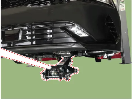
Remove the sub frame. (Refer to Suspension System - "Sub Frame") |
| 18. |
Remove the roll rod support bracket (A).
|
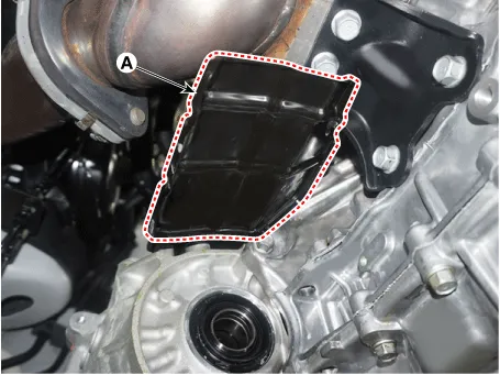
| 19. |
Remove the heat protector (A) by loosening the bolt.
|
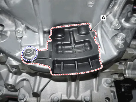
| 20. |
Remove the dust cover (A).
|
| 21. |
Remove the torque converter mounting bolts (A) by rotating the crankshaft in the clockwise.
|

| 22. |
Support the transaxle safely with a jack. |
| 23. |
Loosen the starter lower mounting bolt (A).
|
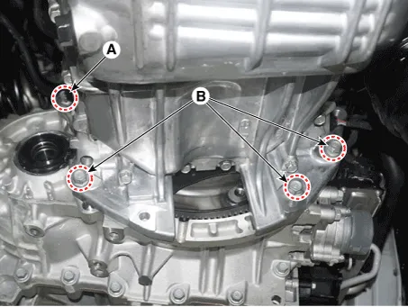
| 24. |
Loosen the transaxle lower mounting bolts (A, B).
|
| 25. |
After separating the transaxle from the engine, remove the transaxle by lowering the jack slowly.
|

| Installation |
| 1. |
Install in the reverse order of removal.
|


Components and components location Component 1. Shift Lever Assembly 2. Shift Cable Assembly Repair procedures Removal 1.
Components and components location Components Location 1. Automatic transaxle 2. Oil filter 3. Mechanical oil pump 4.
Other information:
Kia Optima DL3 2019-2026 Service and Repair Manual: Ventilated and Heated Seat Switch
Schematic diagrams Connector and Terminal Function [Front Seat] [Ventilation+Heater Type / Non-Heater Type] Pin Function Pin Function Ventilation+Heater Type Non-Heater Type Ventilation+Heater Type Non-Heater Type
Kia Optima DL3 2019-2026 Service and Repair Manual: Washer Switch
R
Categories
- Manuals Home
- Kia Optima Owners Manual
- Kia Optima Service Manual
- Engine Control Module (ECM)
- Front Axle Assembly
- External Amp
- New on site
- Most important about car
