Kia Optima DL3: Smart Key System / Smart Key
Repair procedures
| Adjustment |
Smart Key Code Saving
| 1. |
Connect the VCI II in driver side crash pad lower panel, turn the power on KDS. |
| 2. |
Select the vehicle model and then do "Smart key code saving".
|
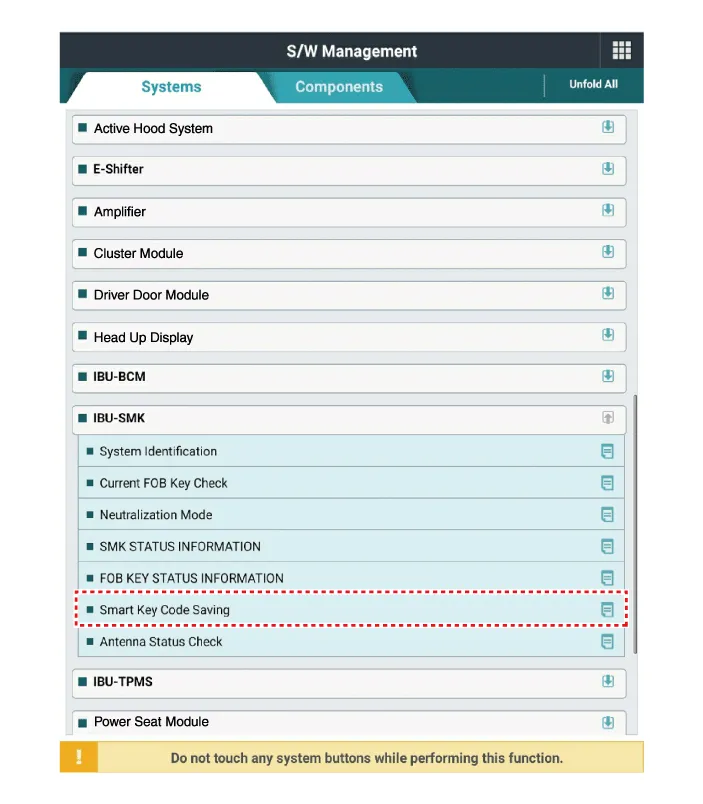
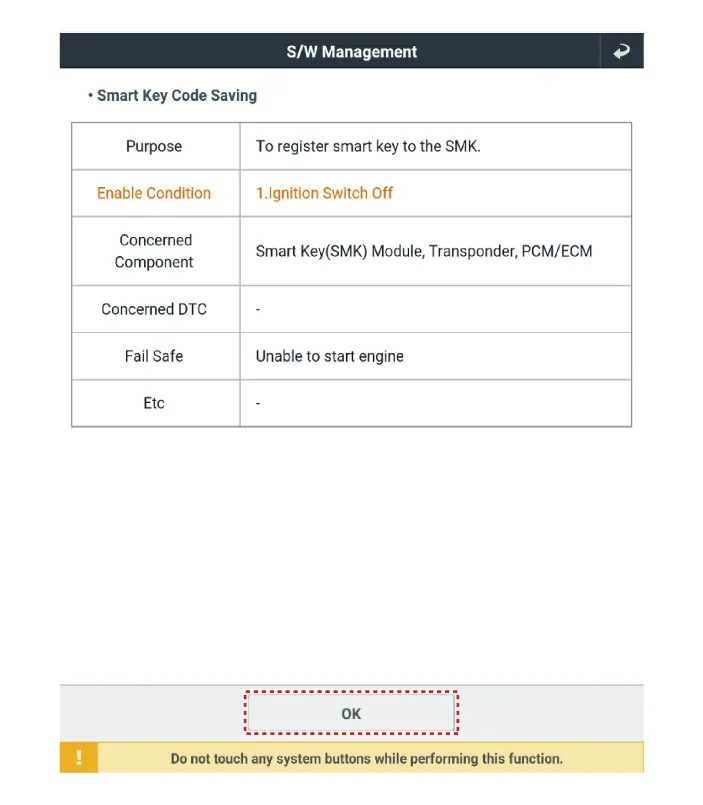
| 3. |
After selecting "Smart key teaching" menu, push "Enter" key, then the screen will be shown as below.
|
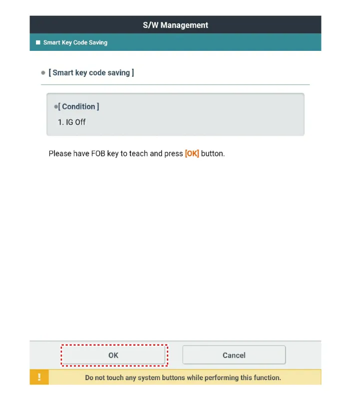
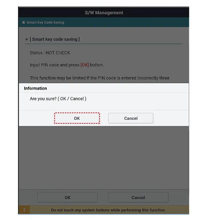
| 4. |
After having the teaching smart key, push "ENTER" key. |
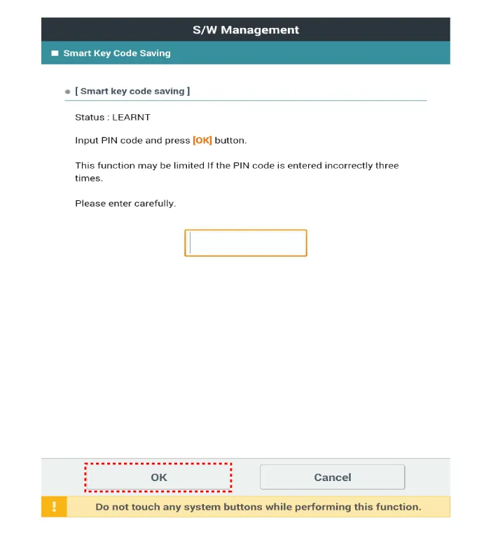
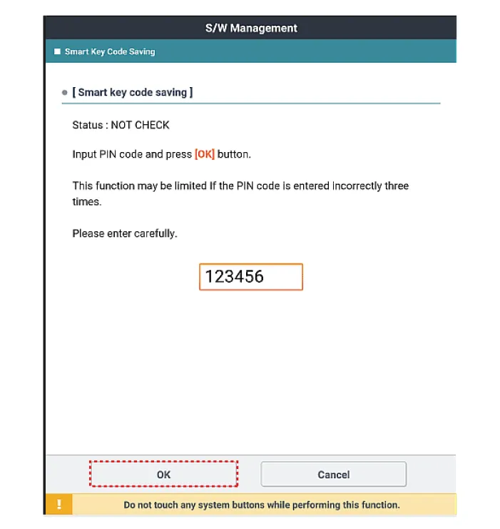
| 5. |
Input the "Pin code" for first key teaching.
|
| 6. |
Confirm the message "First key teaching completed".
|
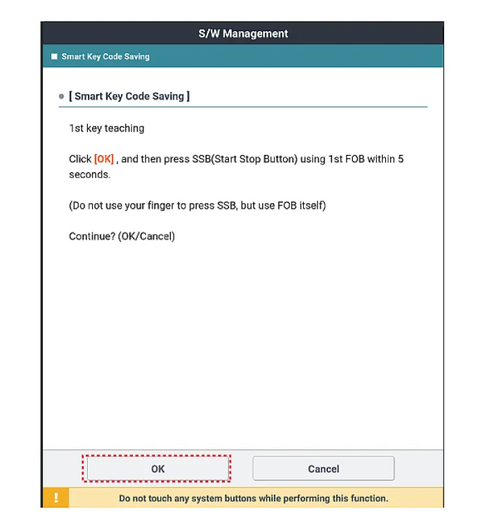
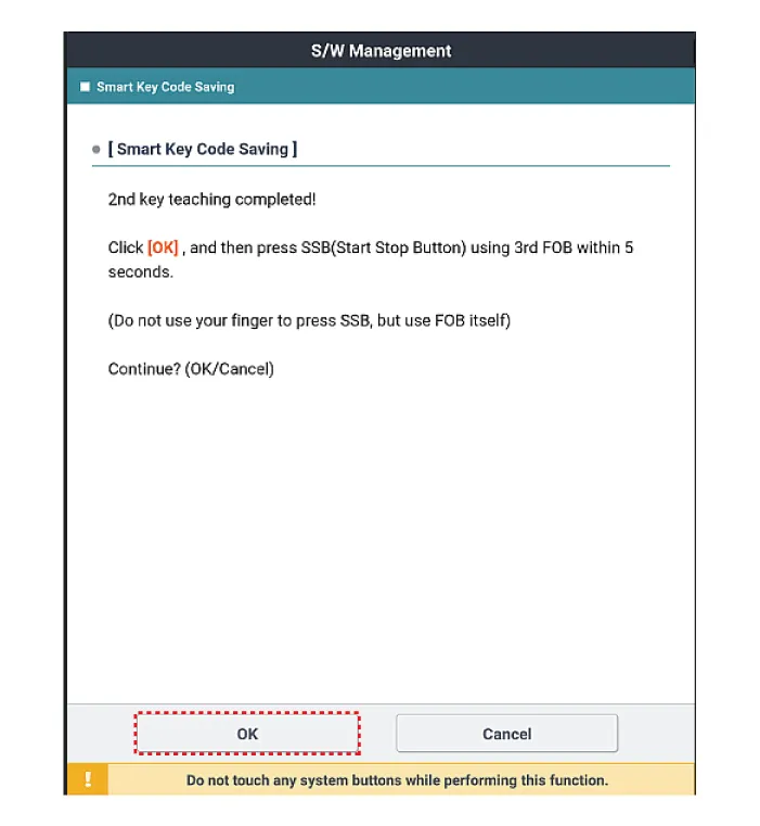
| 7. |
Press the SSB with smart key within 5 sec after pressing "OK".
|
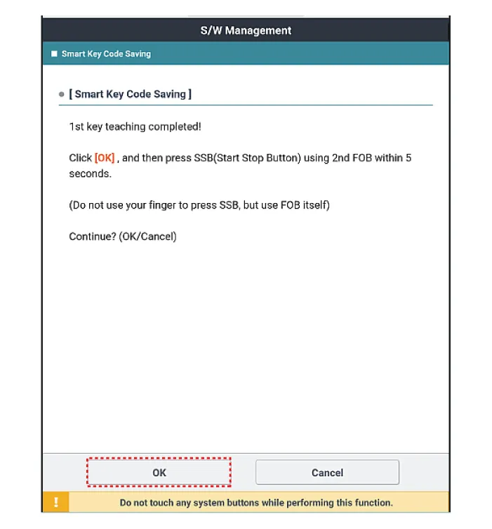
| 8. |
Confirm the message "Second key teaching completed".
|
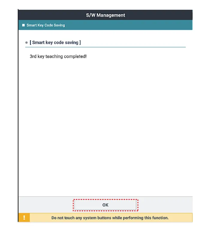
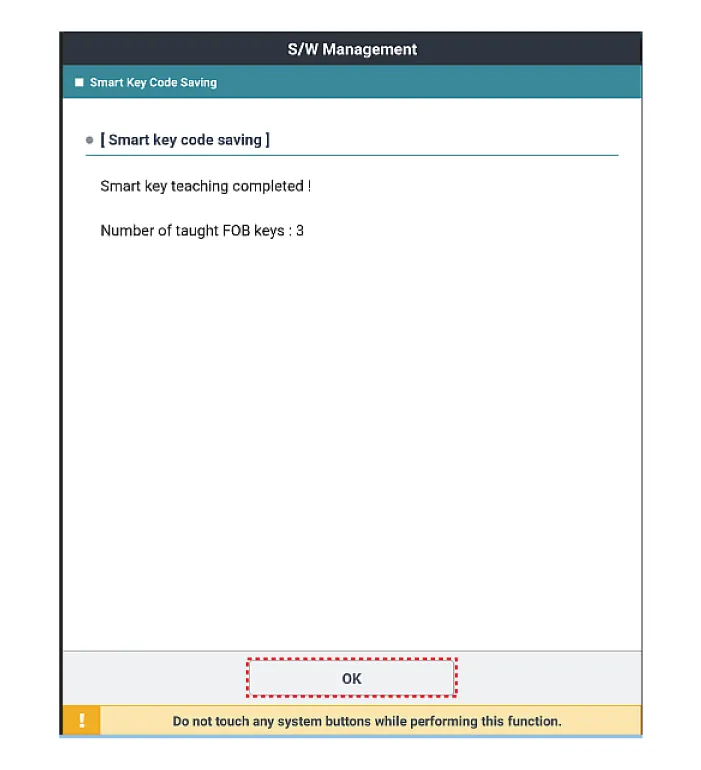
| 9. |
Then the screen will be shown as below when key teaching process is completed.
|
Specifications Specifications Smart Key Unit Items Specification Rated voltage DC 12 V Operation voltage DC 9 - 16 V Operation temperature -40 to 185°F (-40 to 85°C) RF Receiver Items Specification Frequency 433.
Schematic diagrams Connector and Terminal Function Pin Function Connector A Connector B Connector C Connector D 1 - Front washer switch (Output) - Driver outside handle switch (Input) 2 Rear seat belt indicator_Left (Output) - ESCL Enable (Output) Assist outside handle switch (Input) 3 - - ESCL - (Output) - 4 - - - - 5 External buzzer (Output) - - RPM (Input) 6 Rear seat belt indicator_Center (Output) Wiper parking switch (Input) - SSB symbol illumination (+) (Output) 7 Puddle pocket lamp (Output) - ESCL Unlock switch (Input) ACC relay (Output) 8 Rear seat belt indicator_Right (Output) Brake switch (Input) - IGN1 relay (Output) 9 - - - IGN2 relay (Output) 10 Headlamp high switch (Input) Front wiper volume switch (Input) ESCL + (Output) Starter relay (Output) 11 - - Assist outside handle antenna (+) (Output) 12 - LIN4 (Safety ECU) Interior antenna 2 (+) (Output) 13 Rear view switch (Input) PAS Option (Input) Trunk interior antenna 3 (+) (Output) 14 - - Interior antenna 1 (+) (Output) 15 RPAS Power (Output) B-CAN (Low) Bumper antenna (+) (Output) 16 FRAS Power (Output) B-CAN (High) Driver outside handle antenna (+) (Output) 17 PAS/RPAS Power (Input) - - 18 - Ground (Power) - 19 - - - 20 Ground (ECU) Immobilizer power (Output) - 21 - Immobilizer ground (Output) SSB switch 1 (Input) 22 K-Line_Immobilizer - SSB switch 2 (Input) 23 - PAS/RPAS Switch indicator (Output) Clutch IGN lock switch 24 - Front wiper switch (Input) ESCL COM 25 Sunroof status (Input) - Wheel speed sensor (Input) 26 PAS/RPAS Switch (Input) Multifunction switch ground (Input) - 27 ATM Solenoid (Output) Wiper power relay (Output) - 28 LIN3 (Rain sensor) Auto light sensor ground (Output) - 29 LIN2 (ROA) Auto light sensor signal (Input) - 30 LIN1 (PDW-F or PDW-R) Auto light sensor power (Output) Start feed back (Input) 31 Door unlock signal (For IFU) EMS (Output) - Assist outside handle antenna (-) (Output) 32 Light switch (Input) Front wiper high relay (Output) Interior antenna 2 (-) (Output) 33 Fog switch (Input) Front wiper low relay (Output) Trunk interior antenna 3 (-) (Output) 34 IGN2 (Input) Front wiper low backup switch (Input) Interior antenna 1 (-) (Output) 35 IGN1 (Input) P-CAN (Low) Bumper antenna (-) (Output) 36 ACC (Input) P-CAN (High) Driver outside handle antenna (-) (Output) 37 Battery + (ECU) - 38 Battery + (Power) - 39 - - 40 Front heated nozzle (Output) 'P' Position (input) Repair procedures Removal Integrated Body control Unit (IBU) 1.
Other information:
Kia Optima DL3 2019-2026 Service and Repair Manual: Room Lamp
Repair procedures Removal When removing with a flat-tip screwdriver or remover, wrap protective tape around the tools to prevent damage to components. 1.
Kia Optima DL3 2019-2026 Service and Repair Manual: Air Conditioning System
General safety information and caution Instructions (R-134a) When Handling Refrigerant 1. R-134a liquid refrigerant is highly volatile. A drop on the skin of your hand could result in localized frostbite. When handling the refrigerant, be sure to wear gloves.
Categories
- Manuals Home
- Kia Optima Owners Manual
- Kia Optima Service Manual
- Timing Chain
- Battery
- Rear Brake Disc
- New on site
- Most important about car
