Kia Optima DL3: Automatic Transaxle Control System / Shift Cable
Components and components location
| Component |
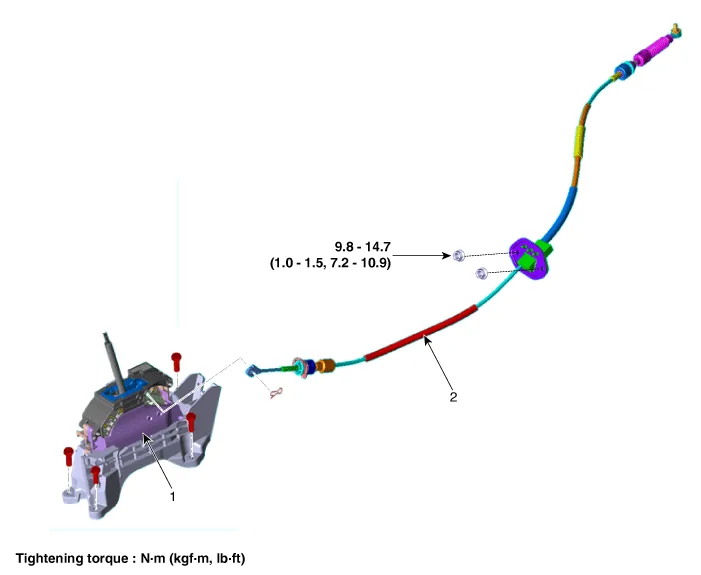
| 1. Shift Lever Assembly |
2. Shift Cable Assembly |
Repair procedures
| Removal |
| 1. |
Shift the gear to "N". |
| 2. |
Remove the battery and battery tray. (Refer to Engine Electrical System - "Battery") |
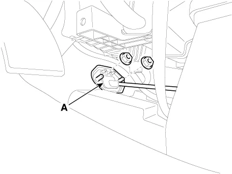
| 3. |
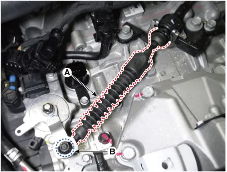
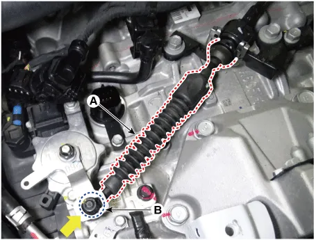
Remove the shift cable (A) from the bracket after loosening a nut (B).
|
| 4. |
Remove the floor console assembly. (Refer to Body - "Floor Console Assembly") |
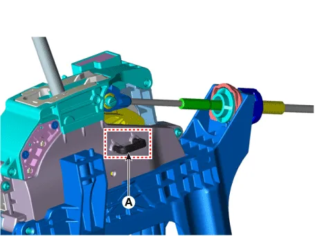
| 5. |
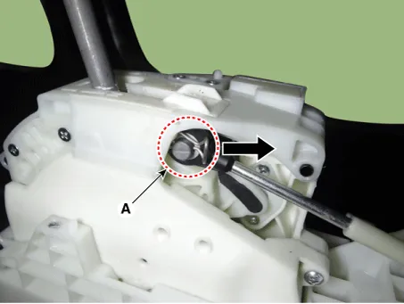
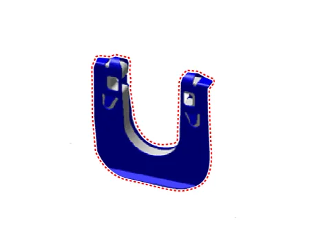
Remove the snap pin (A).
|
| 6. |
Remove the shift cable (A) from the shift lever.
|
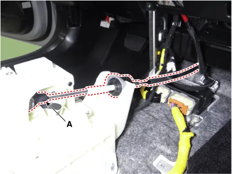
| 7. |
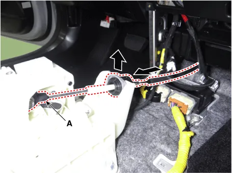
Remove the shift cable retainer (A) after loosening the nuts (B). Then, remove the shift cable by pulling it toward the vehicle interior.
|
| Installation |
| 1. |
Insert "N range fixing pin"(A) of shift lever after checking the shift lever and manual control lever are on "N" range.
|
| 2. |
Install the shift cable retainer (A) by tightening nuts.
|
| 3. |
Insert the snap pin (A) after installing the shift cable.
|


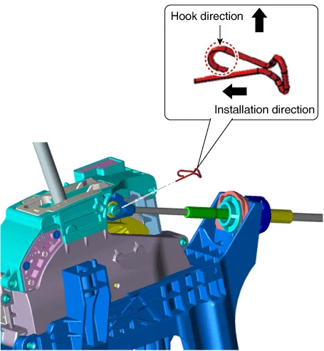
| 4. |
Tighten the nut (B) to the specified torque after removing free play by pushing the shift cable (A) in the direction of the arrow.
|
| 5. |
Remove the N range fixing pin (A).
|
| 6. |
Install the floor console assembly. (Refer to Body - "Floor Console Assembly") |
| 7. |
Install the battery and battery tray. (Refer to Engine Electrical System - "Battery") |
Components and components location Component 1. Shift Lever Assembly 2. Shift Cable Assembly Repair procedures Removal 1.
Components and components location Components 1. Transaxle Support Braket 5. Roll Rod Support Bracket 2.
Other information:
Kia Optima DL3 2019-2026 Service and Repair Manual: Panorama Sunroof
C
Kia Optima DL3 2019-2026 Service and Repair Manual: Heater Unit
Components and components location Component Location 1. Heater unit assembly Compoents 1. Mode control actuator 2. Temperature control actuator [LH] 3. PTC Heater dummy 4.
Categories
- Manuals Home
- Kia Optima Owners Manual
- Kia Optima Service Manual
- Front Axle Assembly
- Rear Brake Disc
- Motor Driven Power Steering
- New on site
- Most important about car
