Kia Optima DL3: Charging System / Battery Sensor
Description and operation
| Description |
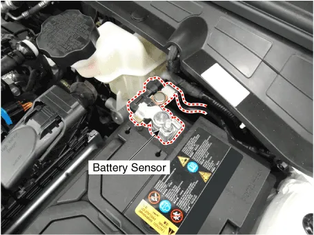
Vehicles have many control units that use more electricity. These units control their own system based on information from diverse sensors. It is important to have a stable power supply as there diverse sensors giving a variety of information. Battery sensor is mounted on battery (-) terminal. It transmits battery voltage, current, temperature information to ECM. ECM controls generating voltage by duty cycle based on these signals.
Repair procedures
| Removal |
| 1. |
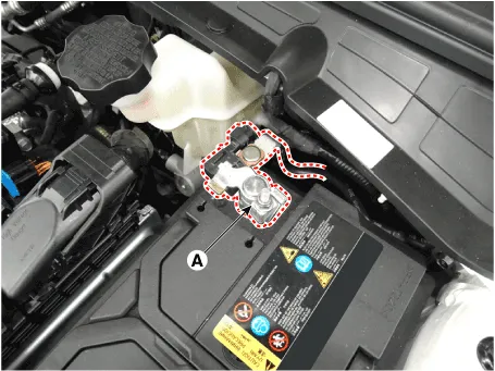
Turn the ignition switch OFF. |
| 2. |
Disconnect the battery (-) terminal (A).
|
| 3. |
Remove the battery. (Refer to Engine Electrical System - "Battery") |
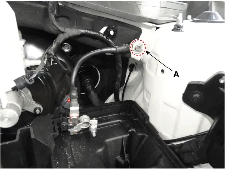
| 4. |
Remove the battery negative (-) cable after removing the bolts (A).
|
| Installation |
| 1. |
Install in the reverse order of removal. |
Description and operation Description 1. The CMF(Closed Maintenance Free) battery is, as the name implies, totally maintenance free and has no removable battery cell caps.
Description and operation Description The starting system includes the battery, starter, solenoid switch, ignition switch, inhibitor switch (A/T), clutch pedal switch (M/T), ignition lock switch, connection wires and the battery cable.
Other information:
Kia Optima DL3 2019-2026 Service and Repair Manual: Evaporator Temperature Sensor
Description and operation Description The evaporator temperature sensor will detect the evaporator core temperature and interrupt compressor relay power in order to prevent evaporator from freezing by excessive cooling. The evaporator temperature sensor has the Negative Temperature Coefficient (NTC).
Kia Optima DL3 2019-2026 Service and Repair Manual: Blower Motor
Repair procedures Inspection 1. Connect the battery voltage and check the blower motor rotation. 2. If the blower motor does not operate well, substitute with a known-good blower motor and check for proper operation.
Categories
- Manuals Home
- Kia Optima Owners Manual
- Kia Optima Service Manual
- Headlamps
- Body Electrical System
- Motor Driven Power Steering
- New on site
- Most important about car
