Kia Optima DL3: Engine Electrical System / Starting System
Description and operation
| Description |
The starting system includes the battery, starter, solenoid switch, ignition switch, inhibitor switch (A/T), clutch pedal switch (M/T), ignition lock switch, connection wires and the battery cable.
When the ignition key is turned to the start position, current flows and energizes the starter motor's solenoid coil.
The solenoid plunger and clutch shift lever are activated, and the clutch pinion engages the ring gear.
The contacts close and the starter motor cranks.
In order to prevent damage caused by excessive rotation of the starter armature when the engine starts, the clutch pinion gear overruns.
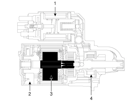
| 1. Solenoid 2. Brush 3. Armature 4. Over runing clutch |
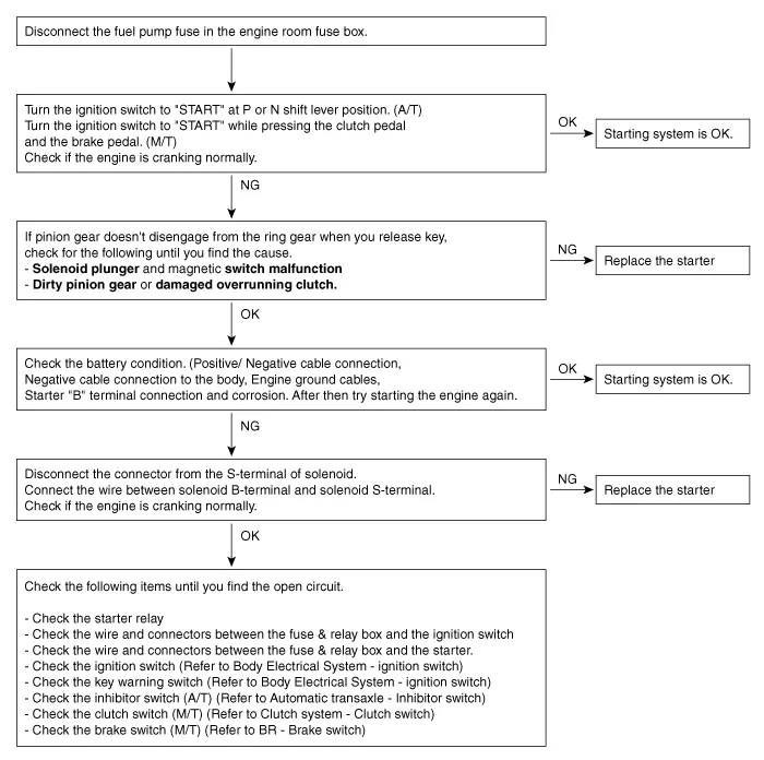
Troubleshooting
| Troubleshooting |
|
Symptom |
Suspect Area |
Remedy |
|
Engine will not crank |
Battery charge low |
Charge or replace battery |
|
Battery cables loose, corroded or worn out |
Repair or replace cables |
|
|
Transaxle range switch (Vehicle with automatic transaxle only) |
Refer to AT group-automatic transaxle |
|
|
Fuse blown |
Replace fuse |
|
|
Starter motor faulty |
Replace |
|
|
Ignition switch faulty |
Replace |
|
|
Engine cranks slowly |
Battery charge low |
Charge or replace battery |
|
Battery cables loose, corroded or worn out |
Repair or replace cables |
|
|
Starter motor faulty |
Replace |
|
|
Starter keeps running |
Starter motor faulty |
Replace |
|
Ignition switch |
Replace |
|
|
Starter spins but engine will not crank |
Short in wiring |
Repair or replace wiring |
|
Pinion gear teeth broken or starter motor |
Replace |
|
|
Ring gear teeth broken |
Replace fly wheel or torque converter |
|

Description and operation Description Vehicles have many control units that use more electricity. These units control their own system based on information from diverse sensors.
Description and operation Description The starting system includes the battery, starter, solenoid switch, ignition switch, inhibitor switch (A/T), clutch pedal switch (M/T), ignition lock switch, connection wires and the battery cable.
Other information:
Kia Optima DL3 2019-2026 Service and Repair Manual: Smart Key System
Specifications Specifications Smart Key Unit Items Specification Rated voltage DC 12 V Operation voltage DC 9 - 16 V Operation temperature -40 to 185°F (-40 to 85°C) RF Receiver Items
Kia Optima DL3 2019-2026 Service and Repair Manual: Compressor
Description and operation Description The compressor is the power unit of the A/C system. It is located on the side of engine block and driven by a V-belt of the engine. The compressor changes low pressure and low temperature refrigerant gas into high pressure and high temperature refrigerant gas.
Categories
- Manuals Home
- Kia Optima Owners Manual
- Kia Optima Service Manual
- Battery
- Timing Chain
- Charging System
- New on site
- Most important about car
