Kia Optima: Brake System / Brake Pedal
Components and components location
| Components |
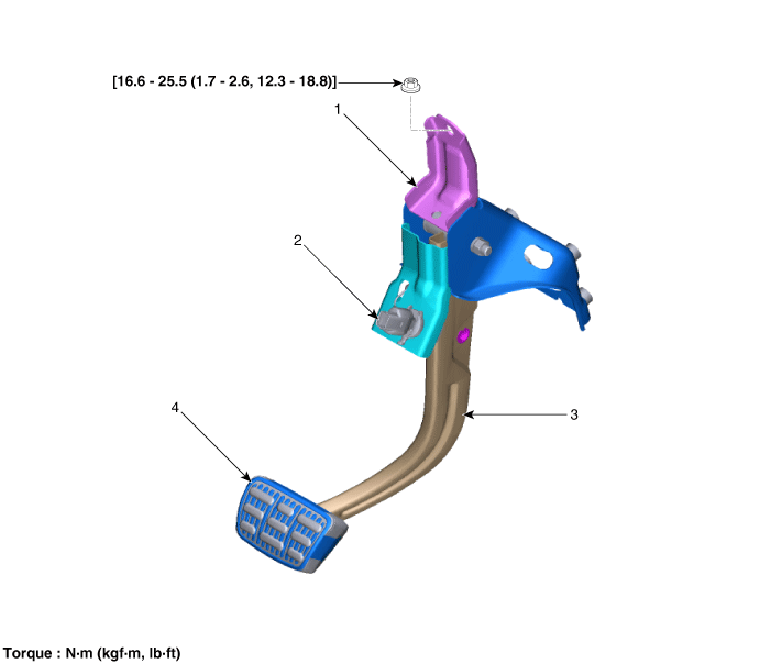
| 1. Brake member assembly 2. Stop lamp switch |
3. Brake pedal arm assembly
4. Brake pedal pad |
Repair procedures
| Removal |
| 1. |
Turn ignition switch OFF and disconnect the negative (-) battery cable. |
| 2. |
Remove the crash pad lower panel. (Refer to Body - "Crash Pad Lower Panel") |
| 3. |
Remove the drive airbag module. (Refer to Restraint - "Drive Airbag Module") |
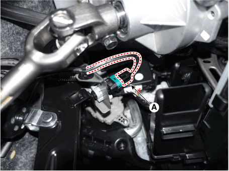
| 4. |
Disconnect the stop lamp switch connector (A).
|
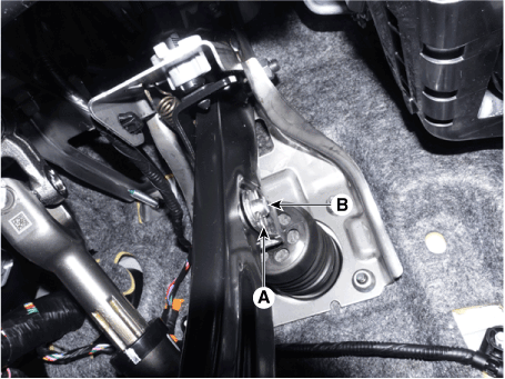
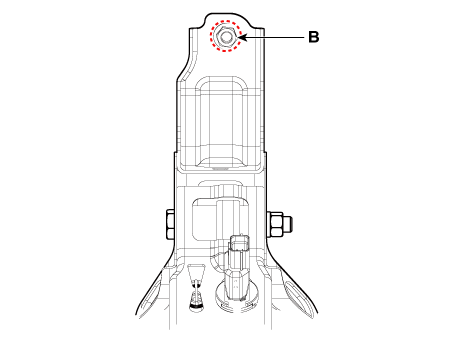
| 5. |
Separate the snap pin (A) and clevis pin (B).
|
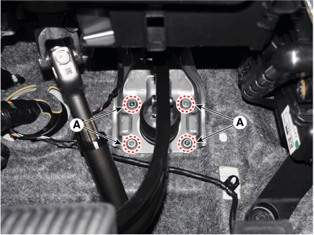
| 6. |
Loosen the nuts (A), (B) and then remove the brake pedal assembly.
|
| Inspection |
| 1. |
Check the brake pedal for bending or twisting. |
| 2. |
Check the brake pedal return spring for damage. |
| 3. |
Check the stop lamp switch. (Refer to Brake System - "Stop Lamp Switch") |
| Installation |
| 1. |
Install in the reverse order of removal.
|

 Brake Line
Components and components location
Components
1. HECU flare nuts.
2. HECU to body mounting nuts.
3. Master cylinder to HECU flare nut.
4. Front brake line tube f ...
 Stop Lamp Switch
Components and components location
Components
1. Brake member assembly
2. Stop lamp switch
3. Brake pedal arm assembly
4. Brake pedal pad
...
Other information:
Kia Optima DL3 2019-2025 Owner's Manual: Back-up lamp bulb replacement
1. Open the trunk lid. 2. Loosen the retaining screw of the trunk lid cover and then remove the cover. 3. Remove the nuts from the vehicle. 4. Disconnect the rear combination lamp (inside) connector. 5. Remove the rear combination lamp (inside) assembly from the body of the vehicle. 6. ...
Kia Optima DL3 2019-2025 Owner's Manual: Easy access function
The system will move the driver's seat automatically as follows: Without smart key system - It will move the driver’s seat rearward when the ignition key is removed and front driver`s door is opened. - It will move the driver’s seat forward when the ignition key is inserted. With sm ...
