Kia Optima DL3: Brake System / Stop Lamp Switch
Components and components location
| Components |
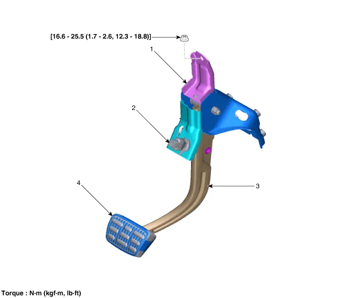
| 1. Brake member assembly 2. Stop lamp switch |
3. Brake pedal arm assembly
4. Brake pedal pad |
Schematic diagrams
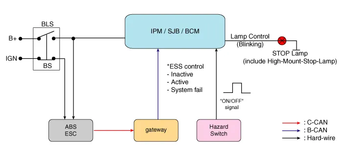
| System Circuit Diagram |
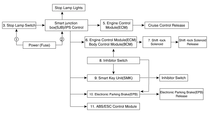
| Schematic Diagram |
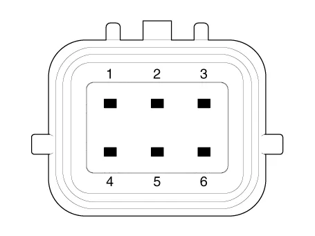
| Terminal Function |

|
Teminal |
Description |
|
1 |
IGN1 |
|
2 |
Engine Control Module (ECM) |
|
3 |
- |
|
4 |
B+ |
|
5 |
Stop Lamp |
|
6 |
Ground |
Troubleshooting
| Troubleshooting |
| 1. |
Part diagnosis
|
| 2. |
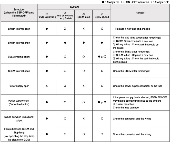
Symptom diagnosis
|
| 3. |
Stop lamp switch system diagnosis
SSEM : Stop Signal Electronic Module |
| 4. |
Refer to DTC guide when the related DTC codes are displayed. |
Repair procedures
| Adjustment |
| 1. |
Turn ignition switch OFF and disconnect the negative (-) battery cable. |
| 2. |
Remove the lower crash pad. (Refer to Body - "Crash Pad") |
| 3. |
Confirm the gap between stop lamp switch and bracket.
|

| 4. |
If the gap between stop lamp switch and bracket is not 1.0-2.0 mm (0.04-0.08 in), check the mounting clip and other part of around stop lamp. |
| 5. |
If there is normal, remove the stop lamp switch and then install again. |
| Inspection |
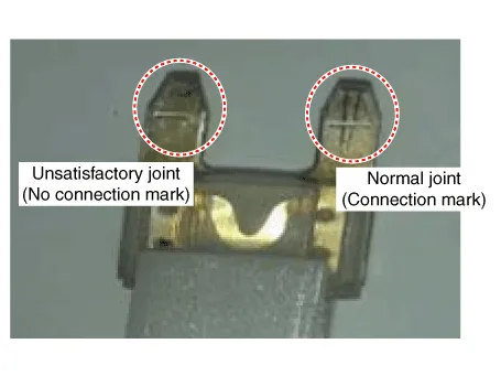
1. Fuse Inspection
Mount the test fuse to the switch fuse and relay fuse part to confirm a normal joint fit.

2. KDS Data Analysis
| 1. |
Analyze KDS data and confirm if there is anything wrong with the stop lamp switch.
|
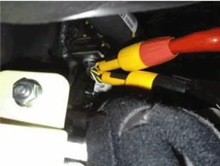
3. Inspection of Connector by Each Part
Check to see whether or not each connector has been damaged, or terminal surge, or incomplete connection has taken place
[Engine Room Junction Box]

[ABS / ESC Control Module]

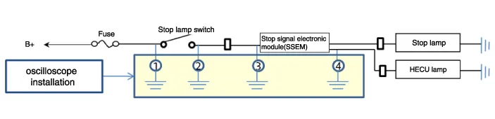
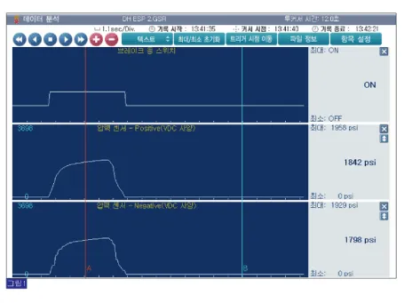
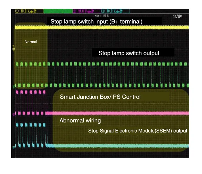
4. Inspect the Stop Lamp Circuit
Connect probe to each terminal wire and confirm oscilloscope waveform.
[Stop Lamp Switch Input / Output]
[Oscilloscope Waveform Screen]
| Removal |
| 1. |
Turn ignition switch OFF and disconnect the negative (-) battery cable. |
| 2. |
Remove the lower crash pad. (Refer to Body - "Crash Pad") |
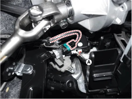
| 3. |
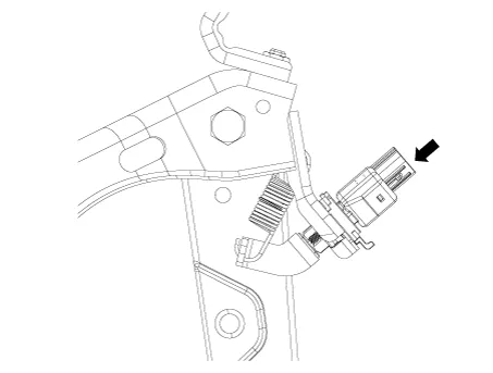
Disconnect the stop lamp switch connector (A).
|
| 4. |
Pull the locking plate (A) as indicated by the arrow.
|

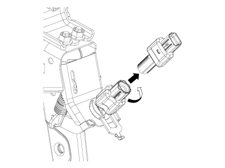
| 5. |
Turn stop lamp switch (A) 45° counterclockwise and remove it.
|
| 6. |
Inspect a removed stop lamp switch along the below procedures.
|
| Installation |
| 1. |
Fix the brake pedal arm and insert fully the stop lamp switch as hiding contact part.
|
| 2. |
After inserting, turn the stop switch (A) 45° clockwise, and then assemble locking plate by pushing.
|

| 3. |
Confirm the gap between stop lamp switch and bracket.
|

| 4. |
Connect the stop lamp switch connector (A).
|
| 5. |
Install the lower crash pad. (Refer to Body - "Crash Pad") |
Components and components location Components 1. Brake member assembly 2. Stop lamp switch 3. Brake pedal arm assembly 4.
Components and components location Components 1. Caliper body 2. Caliper carrier 3. Pad inner shim 4. Brake pad 5.
Other information:
Kia Optima DL3 2019-2026 Service and Repair Manual: High Mounted Stop Lamp
Repair procedures Removal 1. Disconnect the negative battery terminal. 2. Remove the roof trim assembly. (Refer to Body - "Roof Trim Assembly") 3. Disconnect the high mounted stop lamp connector (A).
Kia Optima DL3 2019-2026 Service and Repair Manual: Heater Core
Repair procedures Replacement 1. Disconnect the negative (-) battery terminal. 2. Remove the heater and blower assembly. (Refer to Heater - "Heater Unit") 3. Loosen the mounting screws and remove the heater core cover (A).
Categories
- Manuals Home
- Kia Optima Owners Manual
- Kia Optima Service Manual
- Front Axle Assembly
- Timing Chain
- Lift And Support Points
- New on site
- Most important about car
