Kia Optima DL3: Cylinder Head Assembly / Cylinder Head
Components and components location
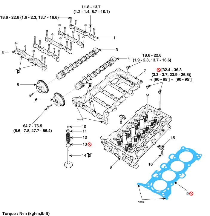
| Components |
|
1. Camshaft bearing cap 2. Camshaft front bearing cap 3. Exhaust camshaft 4. Intake camshaft 5. Exhaust CVVT assembly 6. Intake CVVT assembly |
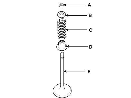
7. Cam carrier 8. Cylinder head 9. Cylinder head gasket 10. Retainer lock 11. Retainer 12. Valve spring |
13. Valve stem seal 14. Valve 15. Swing arm 16. Hydraulic lash adjuster (HLA) |
Repair procedures
| Removal |
Engine removal is not required for this procedure.
|

|

| 1. |
Remove the Battery. (Refer to Engine Electrical System - “Battery”) |
| 2. |
Remove the air cleaner assembly. (Refer to Intake and Exhaust System - “Air Cleaner”) |
| 3. |
Remove the battery tray. (Refer to Engine Electrical System - “Battery”) |
| 4. |
Remove the engine room under cover. (Refer to Engine and Transaxle Assembly - “Engine Room Under Cover”) |
| 5. |
Drain the coolant. (Refer to Cooling System - “Coolant”) |
| 6. |
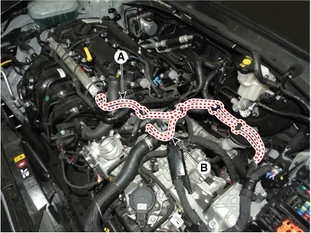
Disconnect the fuel hose (A) and purge control solenoid valve (PCSV) hose (B).
|
| 7. |
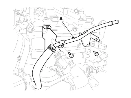
Remove the vacuum pipe (A).
|
| 8. |
Remove the condenser (A).
|
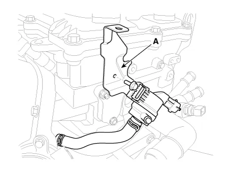
| 9. |
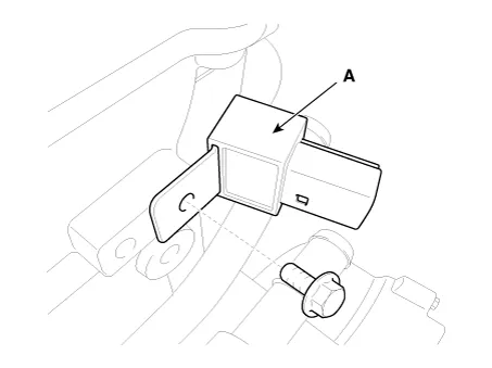
Remove the purge control solenoid valve (PCSV) bracket (A).
|
| 10. |
Remove the delivery pipe. (Refer to Engine Control/Fuel System - “Delivery Pipe”) |
| 11. |
Remove the cylinder head cover. (Refer to Cylinder Head Assembly - “Cylinder Head Cover”) |
| 12. |
Remove the timing chain. (Refer to Timing System - “Timing Chain”) |
| 13. |
Remove the exhaust manifold. (Refer to Intake and Exhaust System - “Exhaust Manifold”) |
| 14. |
Remove the intake manifold. (Refer to Intake and Exhaust System - “Intake Manifold”) |
| 15. |
Remove the water temperature control assembly. (Refer to Cooling System - “Water Temperature Control Assembly”) |
| 16. |
Remove the heater pipe. (Refer to Cooling System - "Thermostat") |
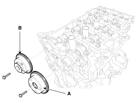
| 17. |
Remove the intake CVVT assembly (A) and exhaust CVVT assembly (B).
|
| 18. |
Remove the camshaft.
|
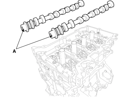
| 19. |
Remove the cam carrier (A).
|
| 20. |
Remove the hydraulic lash adjuster (HLA) (A) and the swing arm (B).
|
| 21. |
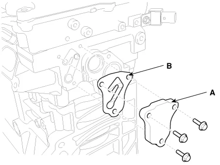
Remove the oil control adapter (A) with the gasket (B).
|
| 22. |
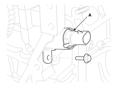
Remove the intake oil control valve (OCV) (A).
|
| 23. |
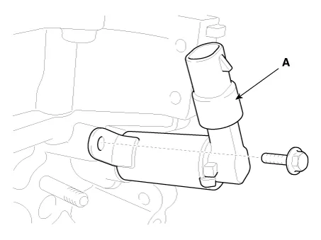
Remove the exhaust oil control valve (OCV) (A).
|
| 24. |
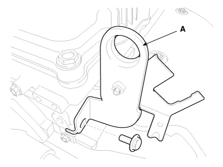
Remove the rear engine hanger (A).
|
| 25. |
Remove the spark plugs. (Refer to Engine Electrical System - “Spark Plug”) |
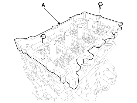
| 26. |
Remove the cylinder head.
|
| Disassembly |
Identify, valves and valve springs as they are removed so that each item can be reinstalled in its original position. |
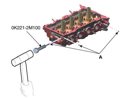
| 1. |
Remove the valves.
|
| Inspection |
Cylinder Head
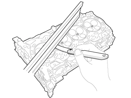
| 1. |
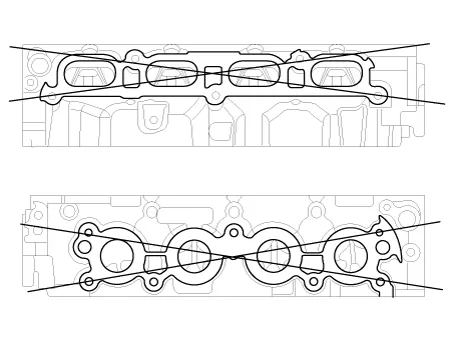
Inspect for flatness.
Using a precision straight edge and feeler gauge, measure the contacting surface of the cylinder block and the manifolds for warpage. If the flatness is greater than maximum, replace the cylinder head.
|
| 2. |
Inspect for cracks. Check the combustion chamber, intake ports, exhaust ports and cylinder block surface for cracks. If cracked, replace the cylinder head. |
Valve And Valve Spring
| 1. |
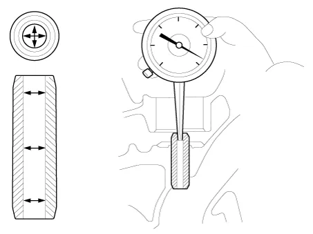
Inspect valve stems and valve guides.
|
| 2. |
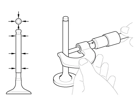
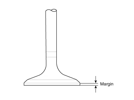
Inspect the valves.
|
| 3. |
Inspect the valve seats and the valve guides.
|
| 4. |
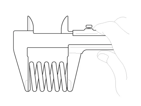
Inspect the valve springs.
|
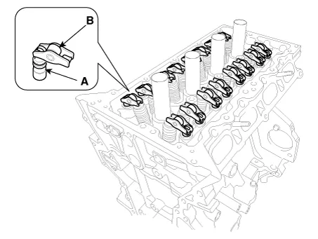
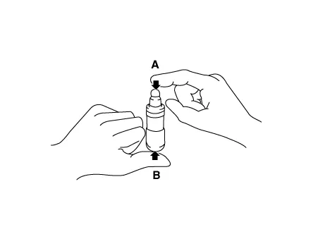
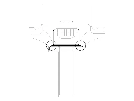
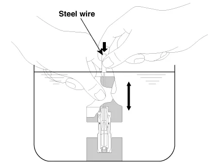
Hydraulic Lash Adjuster (HLA)
With the HLA filled with engine oil, hold A and press B by hand.
If B moves, replace the HLA.
|
Problem |
Possible cause |
Action |
||||
|
1. Temporary noise when starting a cold engine |
Normal |
This noise will disappear after the oil in the engine reaches the normal
pressure. |
||||
|
2. Continuous noise when the engine is started after parking more than 48
hours |
Oil leakage of the high pressure chamber on the HLA, allowing air to get
in |
Noise will disappear within 15 minutes when engine runs at 2000-3000 rpm. If it doesn’t disappear, refer to step 7 below. |
||||
|
3. Continuous noise when the engine is first started after rebuilding cylinder
head |
Insufficient oil in cylinder head oil gallery |
|||||
|
4. Continuous noise when the engine is started after excessively cranking
the engine by the starter motor or band |
|
|||||
|
5. Continuous noise when the engine is running after changing the HLA |
|
|||||
|
6. Continuous noise during idle after high engine speed |
Engine oil level too high or too low |
|
||||
|
Excessive amount of air in the oil at high engine speed |
Check oil supply system. |
|||||
|
Deteriorated oil |
Check oil quality. If deteriorated, replace with specified type. |
|||||
|
7. Noise continues for more than 15 minutes |
Low oil pressure |
Check oil pressure and oil supply system of each part of engine. |
||||
|
Faulty HLA |
Remove the cylinder head cover and press HLA down by hand. If it moves, replace the HLA. |
| Reassembly |
|
| 1. |
Install the valves.
|
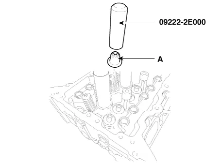
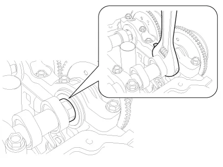
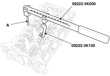
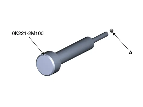
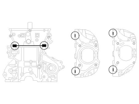
| 2. |
Check if the steel ball (A) is installed in the cylinder head when replacing the cylinder head.
|
| 3. |
If steel ball not installed, be sure to install the steel ball.
|
| Installation |
|
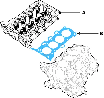
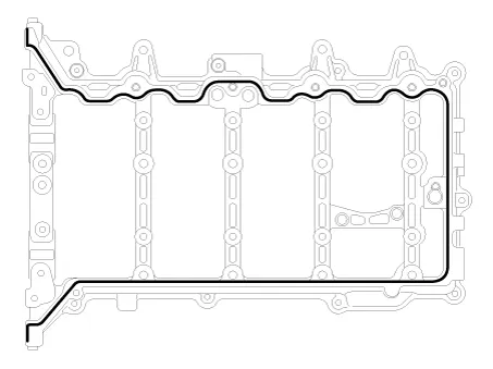
| 1. |
Install the cylinder head gasket (B) on the cylinder block.
|
| 2. |
Place the cylinder head (A) carefully to protect damage to the head gasket (B) during installation.
|
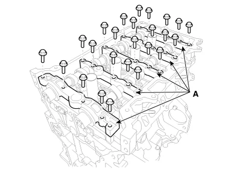
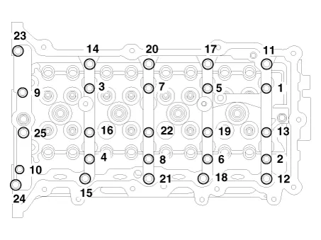
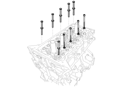
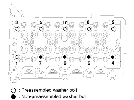
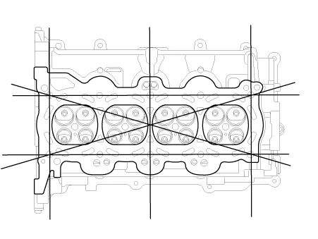
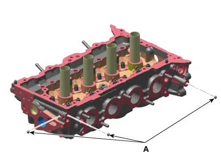
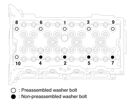
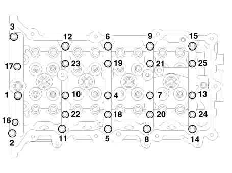
| 3. |
Install the cylinder head bolts with washers. Using SST (09221-4A000), install and tighten the 10 cylinder head bolts, in several passes, in the sequence as shown.
|
| 4. |
Install the rear engine hanger (A).
|
| 5. |
Install the exhaust oil control valve (OCV) (A).
|
| 6. |
Install the intake oil control valve (OCV) (A).
|

| 7. |
Install the oil control adapter (A) with a new gasket (B).
|
| 8. |
Install the hydraulic lash adjuster (HLA)(A) and the swing arm (B).
|
| 9. |
Install the cam carrier.
|
| 10. |
Install the camshafts.
|
| 11. |
Install the intake CVVT assembly (A) and exhaust CVVT assembly (B).
|
| 12. |
Install the other parts reverse order of removal. |
| 13. |
Add all the necessary fluids and check for leaks. Connect KDS. Check for codes, note, and clear. Recheck. |
|
Components and components location Components 1. Camshaft bearing cap 2. Camshaft front bearing cap 3. Exhaust camshaft 4.
Other information:
Kia Optima DL3 2019-2026 Service and Repair Manual: Headlamps
Components and components location Component Location 1. Low beam 2. High beam 3. Daytime Running Light / Position lamp 4. Low assist beam 5. Turn signal lamp Schematic diagrams Connector and Terminal Function Connector Terminal Function
Kia Optima DL3 2019-2026 Service and Repair Manual: Power Mosfet
Description and operation Description It is installed to the DATC and adjusts the fan rpm by precisely controlling the voltage applied to the blower motor. Repair procedures Inspection 1. Turn the ignition switch ON.
Categories
- Manuals Home
- Kia Optima Owners Manual
- Kia Optima Service Manual
- Cooling System
- Front Axle Assembly
- Rear Brake Disc
- New on site
- Most important about car
