Kia Optima DL3: Lighting System / Headlamps
Components and components location
| Component Location |
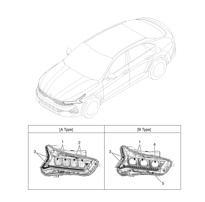
| 1. Low beam 2. High beam 3. Daytime Running Light / Position lamp |
4. Low assist beam 5. Turn signal lamp |
Schematic diagrams
| Connector and Terminal Function |
| Connector |
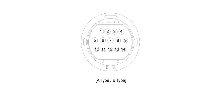
| Terminal Function |
|
Pin |
Function |
|
|
A Type |
B Type |
|
|
1 |
Low beam (+) LED |
Low beam (+) LED |
|
2 |
High beam (+) LED |
High beam (+) LED |
|
3 |
- |
Turn signal lamp (+) LED |
|
4 |
- |
- |
|
5 |
Ground (-) Low beam |
Ground (-) Low beam |
|
6 |
Ground (-) Actuator |
Ground (-) Actuator |
|
7 |
Ground (-) Position/DRL |
Ground (-) Position/DRL |
|
8 |
Ground (-) High beam |
Ground (-) High beam/Turn signal lamp |
|
9 |
Position lamp (+) LED |
Position lamp (+) LED |
|
10 |
DRL (+) LED |
DRL (+) LED |
|
11 |
Leveling device (+) |
Leveling device (+) |
|
12 |
Leveling device signal |
Leveling device signal |
|
13 |
Low beam tell - Tale |
Low beam tell - Tale |
|
14 |
- |
Turn signal tell - Tale |
Repair procedures
| Removal |
Headlamps
| 1. |
Disconnect the negative battery terminal. |
| 2. |
Remove the front bumper assembly. (Refer to Body - "Front Bumper assembly") |
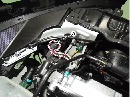
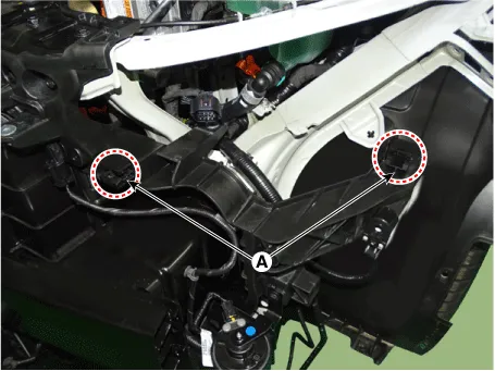
| 3. |
Disconnect the headlamp connector (A).
|
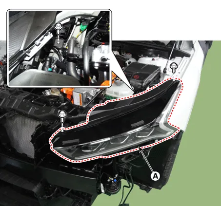
| 4. |
Remove the headlamp (A) by loosening the mounting bolts.
|

| Installation |
| 1. |
Install in the reverse order of removal.
|
| Adjustment |
Head Lamp Aiming
|
If beam-setting equipment is not available, proceed as follows :
| 1. |
Inflate the tires to the specified pressure and remove any loads from the vehicle except the driver, spare tire, and tools. |
| 2. |
The vehicle should be placed on a flat floor. |
| 3. |
Draw vertical lines (passing through respective headlamp centers) and a horizontal line (passing through center of headlamps) on the screen. |
| 4. |
If headlamp leveling device is equipped, adjust the headlamp leveling device switch with 0 positions. |
| 5. |
With the headlamps and battery in normal condition, aim the headlamps so the brightest portion falls on the horizontal and vertical lines. |
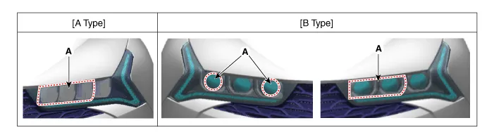
| 6. |
Cover the headlamp outer projection (A) and set the cut-off position.
[A Type] A : Vertical (High/Low beam) B : Horizontal (High/Low beam)
[B Type] A : Vertical (High/Low beam) B : Horizontal (High/Low beam)
|
Headlamp Aiming Point
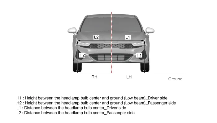
[A Type]
|
Vehicle condition |
H1 |
L1 |
L2 |
Note |
|
Empty |
698 (27.4803) |
744 (29.2913) |
ALL DIM in mm (in.) |
|
|
1 person on board |
693 (27.2834) |
|||
[B Type]
|
Vehicle condition |
H1 |
H2 |
L1 |
L2 |
Note |
|
Empty |
697 (27.4409) |
684 (26.9291) |
751 (29.5669) |
661 (26.0236) |
ALL DIM in mm (in.) |
|
1 person on board |
692 (27.2440) |
679 (26.7322) |
|

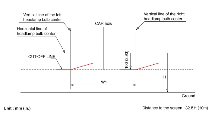
| 1. |
If headlamp leveling device is equipped, adjust the headlamp leveling device switch with 0 positions. |
| 2. |
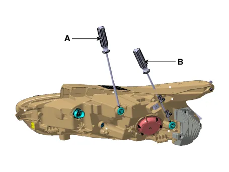
Turn the low beam on without driver aboard. |
| 3. |
The low beam cut-off line should be projected as shown in the picture.
|
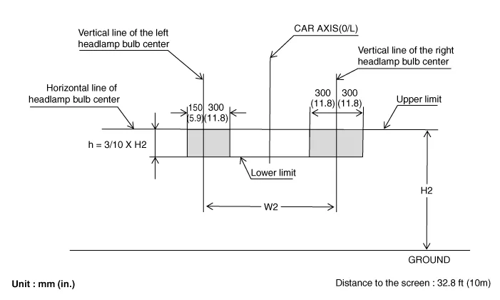
| 4. |
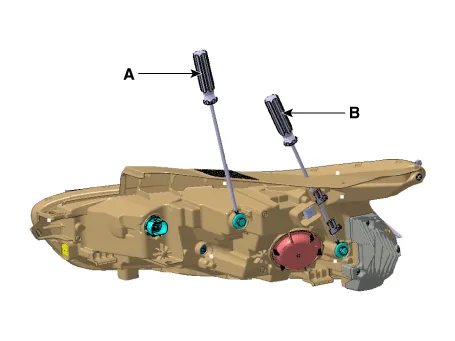
Turn the high beam on without driver aboard. |
| 5. |
The hot zone should be projected in the allowable range shown in the picture.
|
Schematic diagrams Connector and Terminal Function Repair procedures Removal 1. Disconnect the negative battery terminal.
Repair procedures Removal 1. Disconnect the negative battery terminal. 2. Remove the roof trim assembly.
Other information:
Kia Optima DL3 2019-2026 Service and Repair Manual: Auto Defogging Sensor
Description and operation Description The auto defogging sensor is installed on the front window glass. The sensor judges and sends signal if moisture occurs to blow out wind for defogging. The air conditioner control module receives signal from the sensor and restrains moisture and eliminate defog by controlling the intake actu
Kia Optima DL3 2019-2026 Service and Repair Manual: Cluster Ionizer
Components and components location Components Location 1. Condenser Description and operation Description The cluster ionizer makes disinfection and decomposition of bad smell from the air-conditioner or inflow air.
Categories
- Manuals Home
- Kia Optima Owners Manual
- Kia Optima Service Manual
- Suspension System
- Body (Interior and Exterior)
- Timing Chain
- New on site
- Most important about car
