Kia Optima DL3: ESC (Electronic Stability Control) System / ESC Control Module
Components and components location
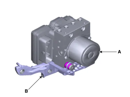
| Components |
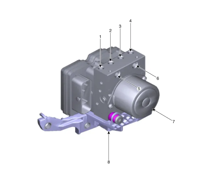
| 1. Front - right (FR) 2. Rear - left (RL) 3. Rear - right (RR) 4. Front - left (FL) |
5. MC2 6. MC1 7. ESP control module (HECU) 8. Bracket |
Repair procedures
| Removal |
| 1. |
Turn ignition switch OFF and disconnect the negative (-) battery cable. |
| 2. |
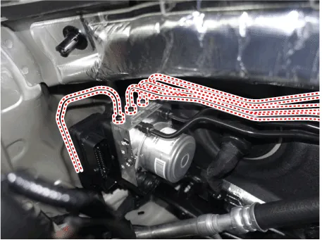
Pull up the lock of the HECU connector and then disconnect the connector (A).
|

| 3. |
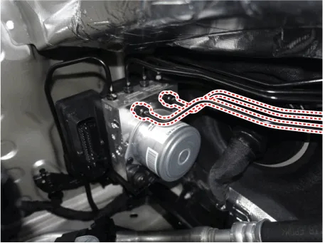
Separate the brake tubes from the HECU by unlocking the nuts (6-ea) couterclockwise using a spanner.
|
| 4. |
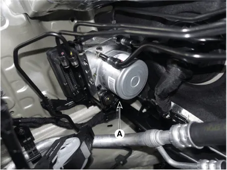
Loosen the ESC control module mounting nut (A) and then remove the ESC control module from the vehicle.
|
| 5. |
Separate the bracket (B) after remove the mounting bolt from the HECU (A).
|
| Installation |
| 1. |
Install in the reverse order of removal. |
| 2. |
After installation, bleed the brake system. (Refer to Brake system - "Brake Bleeding Procedures") |
| 3. |
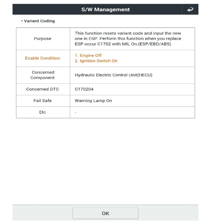
Conduct the Variant coding. |
| 4. |
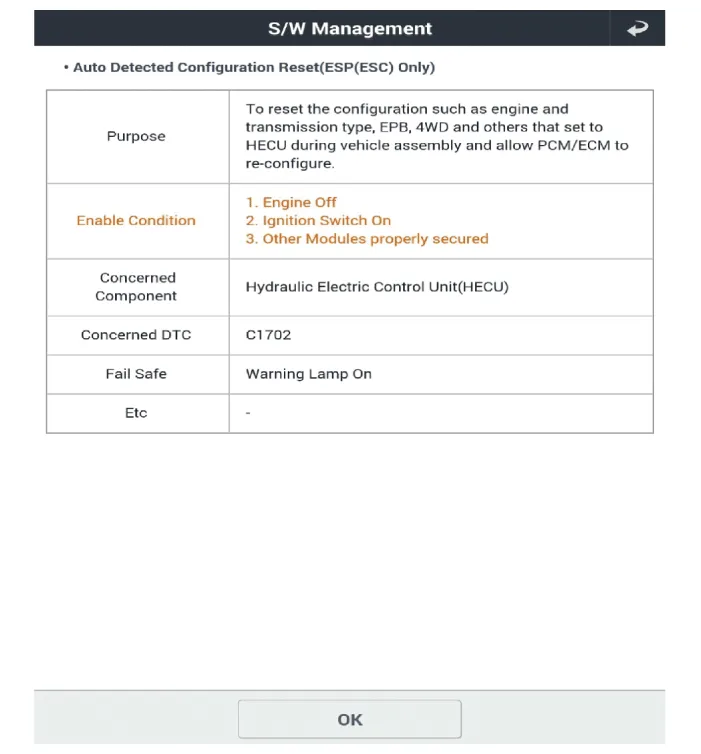
Conduct the Auto Detected Sensor Calibration. |
| 5. |
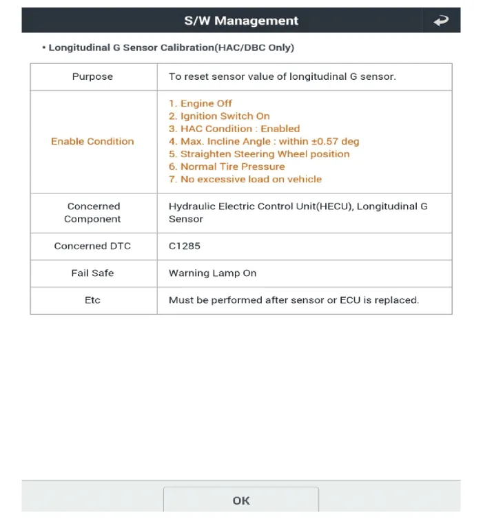
Conduct the Longitudinal G Sensor Calibration. |
| 6. |
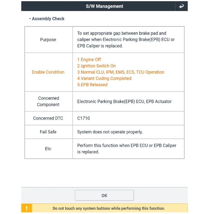
After replacing the ESC control module execute the "Assembly Check (ECU replacement)" of the additional function to check that the mounting is successful. |
| Diagnostic procedure by using diagnostic device |
Perform diagnostic procedure by using diagnostic device as shown below:
Connect self-diagnosis connector (16pins) located under the driver side crash pad to self-diagnosis device, and then turn the self-diagnosis device after key is ON.
Select the "vehicle model" and "ABS/ESC" on KDS vehicle selection screen, then select OK.
[Variant Coding]

[Auto Detected Sensor Calibration]
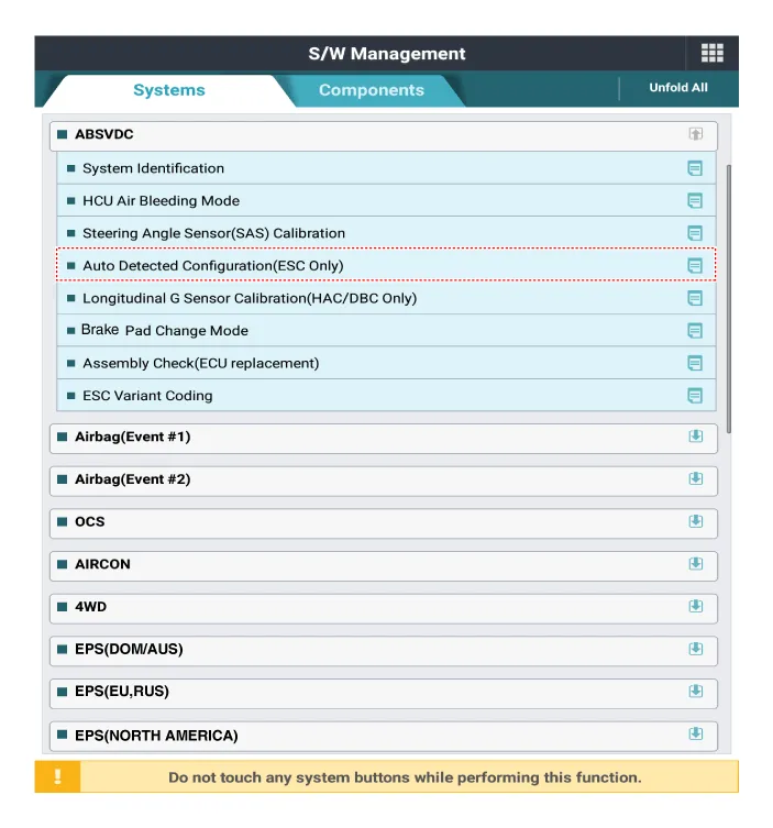
[Longitudinal G Sensor Calibration]

[Assembly Check]

Components and components location Components 1. ESC control module (HECU) 2. Front wheel speed sensor 3. Rear wheel speed sensor 4.
Description and operation Description 1. The ESC OFF switch is for the user to turn off the ESC system. 2.
Other information:
Kia Optima DL3 2019-2026 Service and Repair Manual: Lumbar Support System
Repair procedures Inspection 1. Remove the front seat back. (Refer to Body - "Front Seat Back Cover") 2. Disconnect the connector (A). 3. When the battery power is supplied to the motor connector, check the motor for smooth operation.
Kia Optima DL3 2019-2026 Service and Repair Manual: Heater Unit
Components and components location Component Location 1. Heater unit assembly Compoents 1. Mode control actuator 2. Temperature control actuator [LH] 3. PTC Heater dummy 4.
Categories
- Manuals Home
- Kia Optima Owners Manual
- Kia Optima Service Manual
- Engine Electrical System
- Engine Mechanical System
- Suspension System
- New on site
- Most important about car
